The utility model discloses a water meter protection valve, which includes a valve body, a valve cover, a valve rod, and a gate plate connected to the bottom end of the valve rod. Both ends of the valve body are respectively provided with a water inlet end and a water outlet end. The valve body is internally provided with a flowing water channel for medium circulation. A cavity connected to the flowing water channel is arranged inside the valve body on the side opposite to the gate plate relative to the water outlet end. The utility model further includes a check mechanism, which comprises a valve core, a sealing ring, a pressure ring, a spring, and a positioning ring. These components are arranged inside the cavity and sequentially sleeved on the valve core towards the water outlet end. The outer circumferential wall of the valve core is provided with a convex ring located inside the flowing water channel and abutting against the sealing ring. The sealing ring is located at the connection between the flowing water channel and the cavity, and is used to control the connection and disconnection between the two. The utility model can solve the phenomenon of water meter rotation and reverse rotation caused by pressure difference in the pipe network. At the same time, the minimum starting flow rate of this valve is greater than the minimum starting flow rate of the water meter, which can solve the problem of dripping and leakage in residential water use.
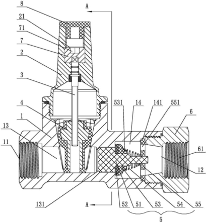
1. A water meter protection valve, comprising a valve body, a valve cover, a valve rod, and a gate plate connected to the bottom end of the valve rod. The two ends of the valve body are respectively provided with an inlet end and an outlet end. The valve body is internally provided with a flowing water channel for medium circulation. The utility model is characterized in that: a cavity communicating with the flowing water channel is arranged on one side of the valve body opposite to the gate plate and located at the outlet end; the utility model further comprises a check mechanism, which comprises a valve core, a sealing ring, a pressure ring, a spring, and a positioning ring. The sealing ring, pressure ring, spring, and positioning ring are arranged in the cavity and sequentially sleeved on the valve core towards the outlet end. The outer circumferential wall of the valve core is provided with a convex ring located in the flowing water channel and abutting against the sealing ring. The sealing ring is located at the communication point between the flowing water channel and the cavity, and is used to control the communication and cutoff between the two. The two ends of the spring are respectively abutted against the pressure ring and the positioning ring. The positioning ring is provided with a through port communicating with the cavity. The valve core can reciprocate towards the positioning ring. The outlet end is provided with a connecting head threadedly connected thereto, and the connecting head is provided with a through hole communicating with the flowing water channel.
2. A water meter protection valve according to claim 1, characterized in that a guide block is provided on the side of the convex ring facing the water inlet end.
3. A water meter protection valve according to claim 2, characterized in that at least four guide blocks are provided, and are circumferentially arranged on the outer circumferential wall of the valve core.
4. A water meter protection valve according to claim 3, characterized in that a protrusion is provided in the water flow channel on the side of the guide block facing the inlet end, which protrusion abuts against the guide block.
5. A water meter protection valve according to claim 1, characterized in that the spring adopts a tower spring, and the end of the tower spring with a smaller inner diameter abuts against the end face of the positioning ring.
6. A water meter protection valve according to claim 5, characterized in that a protrusion is provided on the end face facing the pressure ring, and the end of the tower spring with a larger inner diameter is sleeved on the protrusion.
7. A water meter protection valve according to claim 1, characterized in that a limit slot adapted to the positioning ring is provided in the cavity.
8. A water meter protection valve according to claim 1, characterized in that a groove is provided at the top of the valve cover, the top of the valve rod extends upward into the groove, and a lock block fitted over the top of the valve rod is provided in the groove, with a lock hole provided at the top of the lock block.
9. A water meter protection valve according to claim 8, characterized in that the top of the valve cover is provided with a sealing cover that is threadedly connected to the groove.
10. A water meter protection valve according to claim 1, characterized in that the valve body is made of ductile iron, and its inner and outer surfaces are sprayed with epoxy resin powder.