Your location:

/ Technology / Technology research and development

Kaiwei Xi

KAI WEI XI
  • Technology research

  • Quality management

  • Download

Contact Us
  • Phone:+86 (577)6730 7899
  • Mobile:+86 150 6844 4310
  • Fax:+86(577)6738 7099
  • Email:sales@kaiweixi.com
  • Address:No.1 Linxia Road, Oubei Street, Yongjia County, Zhejiang Province, China
  • Website:https://www.kaiweixi.com
  • soft-sealed gate valve patented

    soft-sealed gate valve patented

       The utility model discloses a novel soft-seal gate valve, which includes a valve body, a valve cover, a valve rod, a valve chamber, and a rubber-coated gate plate. The valve rod penetrates through the valve cover and is connected to the rubber-coated gate plate. The valve chamber includes a medium channel for medium circulation and a connecting chamber that is connected to the medium channel and corresponds to the valve cover. The rubber-coated gate plate is adapted to the connecting chamber and used to cut off or connect the medium channel. The medium channel includes an inlet end and an outlet end. Guide rails are arranged on the inner wall of the connecting chamber on both sides opposite to the rubber-coated gate plate. Both sides of the rubber-coated gate plate are provided with metal sliders, and the metal sliders are provided with sliding grooves that are adapted to the guide rails. Compared to existing soft-seal gate valves, the utility model has good sealing performance, convenient disassembly and assembly, and a long service life for the rubber-coated gate plate.

    1. A novel soft-seal gate valve comprises a valve body, a valve cover, a valve rod, a valve chamber, and a rubber-coated gate plate. The valve rod penetrates through the valve cover and is connected to the rubber-coated gate plate. The valve chamber includes a medium passage for medium circulation and a connecting chamber connected to the medium passage and corresponding to the valve cover. The rubber-coated gate plate is fitted to the connecting chamber and used to cut off or connect the medium passage. The medium passage includes an inlet end and an outlet end. The utility model is characterized in that guide rails are arranged on both sides of the rubber-coated gate plate on the inner wall of the connecting chamber, metal sliding blocks are arranged on both side walls of the rubber-coated gate plate, sliding grooves adapted to the guide rails are opened on the metal sliding blocks, a sealing groove is opened on the top of the valve cover in the axial direction relative to the valve rod, a clamping block is arranged at the opening of the sealing groove, at least three clamping blocks are arranged circumferentially at intervals relative to the central axis of the sealing groove, a sealing seat fitted to and sleeved on the valve rod is arranged inside the sealing groove, a fixed block corresponding to the rotational fit of the clamping block is arranged on the outer circumferential wall at the bottom of the sealing seat, a pressing block abutting against the top surface of the valve cover is arranged on the top of the sealing seat, and a rubber sleeve is sleeved on the top of the valve cover.

    2. A novel soft-seal gate valve according to claim 1, characterized in that a limit opening is provided at the position on the pressure block corresponding to the gap between two adjacent clamping blocks, a limit groove is provided on the end face of the pressure block, a thrust stopper is provided on the sealing seat, and the thrust stopper comprises a fixed disc adapted to the limit groove and a thrust block provided on the outer circumferential wall of the fixed disc and adapted to the limit opening.

    3. A novel soft seal gate valve according to claim 2, characterized in that a limiting block is arranged on the outer circumferential wall of the sealing seat at a position between two adjacent fixing blocks, and a clamping groove adapted to the limiting block is provided on the thrust block.

    4. A novel soft seal gate valve according to claim 1, characterized in that a stepped groove is provided in the valve body at the inlet end, and a filter screen is arranged inside the stepped groove.

    5. A novel soft-seal gate valve according to claim 4, characterized in that the side of the filter screen facing the inlet end is provided with a flow dividing device, which comprises a fixing ring that fits with interference with the inner wall of the stepped groove, a connecting column located on the central axis of the fixing ring, and a flow dividing plate connected to the fixing ring and the connecting column. The side of the stepped groove located on the inlet end facing the fixing ring is provided with an inner groove, and an elastic snap ring is arranged in the inner groove.

    6. A novel soft seal gate valve according to claim 5, characterized in that the side wall of the diverter plate facing the inlet end has a triangular cross-section.

    7. A novel soft seal gate valve according to claim 5, characterized in that one end of the connecting column facing the inlet end is hemispherical

    12-11

    2025

  • Dynamic balance electric control valve Patent

       The utility model provides a dynamically balanced electric regulating valve, which includes a valve body, a valve cover, a valve rod, a valve core installed inside the valve body and connected to the valve rod, and an actuator installed on the valve cover and connected to the top end of the valve rod. The valve body is internally provided with a water inlet chamber, a valve cavity, and a water outlet chamber in order towards the direction of medium flow. The valve core is in the shape of a bucket with its opening facing downwards. The valve core is located inside the valve cavity and is used for connecting or cutting off between the water inlet chamber and the valve cavity. The top of the valve core is provided with a through port for medium circulation. Above the through port, there is a filter cover detachably connected to the valve core. The valve rod is provided with a step, and the outside of the step is covered with an elastic sleeve that fits it. The top of the filter cover is provided with a fixing hole that fits the elastic sleeve. This utility model can filter the medium, is simple to install, time-saving, labor-saving, and can reduce the medium pressure inside the valve body, extending the service life of the valve core.

    1. A dynamic balance electric regulating valve, comprising a valve body, a valve cover, a valve rod, a valve core installed inside the valve body and connected to the valve rod, and an actuator installed on the valve cover and connected to the top end of the valve rod. Its characteristic lies in that the valve body is sequentially provided with an inlet chamber, a valve cavity, and an outlet chamber in the direction of medium flow. The valve core is in the shape of a bucket with an opening facing downwards. The valve core is located inside the valve cavity and is used for connecting or cutting off between the inlet chamber and the valve cavity. The top of the valve core is provided with a port for medium circulation. Above the port, there is a filter cover detachably connected to the valve core. The valve rod is provided with a step, and the outside of the step is covered with an elastic sleeve that fits it. The top of the filter cover is provided with a fixing hole that fits the elastic sleeve.

    2. A dynamic balance electric regulating valve according to claim 1, characterized in that the bottom of the valve body is provided with a downward-opening groove, which is connected to the valve cavity through a through hole. A bottom cover connected to the valve body is arranged below the groove, and a pressure relief mechanism is arranged inside the groove. The pressure relief mechanism comprises a force-receiving member, a pressure plate connected to the force-receiving member, and a first spring arranged below the pressure plate and abutting against the bottom cover. The force-receiving member comprises a flow diversion block protruding from the through hole and a connecting rod connected to the flow diversion block, and the connecting rod passes through the pressure plate and is locked and fixed by a nut.

    3. A dynamic balance electric regulating valve according to claim 2, characterized in that the top end of the pressure plate is pressed against the top wall of the groove, the bottom of the pressure plate is provided with a boss, and the top end of the first spring is sleeved on the boss.

    4. A dynamic balance electric control valve according to claim 1, characterized in that the valve rod is arranged through the valve cover, a sealing cover threadedly connected to the valve cover is sleeved on the valve rod, a convex ring abutting against the valve cover is arranged on the outer circumferential wall of the sealing cover, a nut cover threadedly connected to the sealing cover is arranged at the connection between the sealing cover and the valve rod, an installation groove is arranged at the connection between the nut cover and the valve rod, a plurality of O-rings adapted to the valve rod are stacked in the installation groove, and a packing gland threadedly connected to the installation groove is arranged above the O-rings.

    5. A dynamic balance electric control valve according to claim 4, characterized in that a second spring is arranged between the packing gland and the O-ring.

    6. A dynamic balance electric control valve according to claim 5, characterized in that a sealing ring adapted to the valve rod is arranged inside the nut cover below the installation groove.

    7. A dynamic balance electric control valve according to claim 6, characterized in that the bottom of the sealing cover is provided with a thrust ring that is threadedly connected to the sealing cover and abuts against the bottom end of the valve cover.

    8. A dynamic balance electric regulating valve according to claim 1, characterized in that the top surface of the elastic sleeve is higher than the top surface of the filter cover.

    9. A dynamic balance electric control valve according to claim 8, characterized in that the filter cover is connected to the valve core through threads.

    12-11

    2025

  • Wafer-type ball valve patented

       The utility model provides a wafer-type float valve, which includes a valve body and a driving mechanism. The valve body is provided with a through medium channel in the axial direction, and is tubular in shape. It also includes a butterfly plate that fits and seals with the inner wall of the medium channel. The driving mechanism comprises a valve shaft that passes through the valve body and is connected to the butterfly plate, a valve rod connected to the outer end of the valve shaft in the radial direction, and a float ball connected to the valve rod. The valve rod is provided with a limit bolt that is threadedly connected to the valve body in the swinging direction. The butterfly plate can rotate relative to the valve body. The front end of the valve body at the inlet of the medium channel is provided with a filter screen, which is hollow and hemispherical in shape. The end face of the valve body opposite the filter screen is provided with an annular groove, and the open end of the filter screen is provided with a raised edge that is embedded in the annular groove. The utility model can filter the medium, is simple to install, time-saving, labor-saving, small in size, widely applicable, and can reduce the impact force of the medium on the butterfly plate.

    1. A double-clip type float valve, comprising a valve body and a driving mechanism. The valve body is provided with a through medium channel in the axial direction. It is characterized in that the valve body is tubular and further comprises a butterfly plate that fits and seals with the inner wall of the medium channel. The driving mechanism comprises a valve shaft passing through the valve body and connected to the butterfly plate, a valve rod connected to the outer end of the valve shaft in the radial direction, and a float connected to the valve rod. The valve rod is provided with a limit bolt threadedly connected to the valve body in the swinging direction. The butterfly plate is rotatable relative to the valve body. The front end of the valve body located at the inlet of the medium channel is provided with a filter screen. The filter screen is hollow and hemispherical. The end surface of the valve body opposite the filter screen is provided with an annular groove. The open end of the filter screen is provided with a convex edge embedded in the annular groove.

    2. A wafer-type float valve according to claim 1, characterized in that the valve rod penetrates one end of the valve shaft located outside the valve body, and is threadedly engaged with the valve rod through a nut to clamp the valve shaft and achieve positioning of the valve rod.

    3. A wafer-type ball valve according to claim 2, characterized in that a step is provided at the position on the valve shaft connected to the valve body, a groove is provided at the position on the outer circumferential wall of the valve body corresponding to the step, and a gland is sleeved on the valve shaft, which is threadably connected to the groove and abuts against the step.

    4. A wafer-type ball valve according to claim 3, characterized in that a sealing groove is provided on the side of the groove facing the butterfly plate, and a sealing ring sleeved on the valve shaft is arranged in the sealing groove.

    5. A wafer-type ball valve according to claim 1, characterized in that an inner groove is provided on the side wall within the annular groove, and an elastic snap ring, which is used to press the convex edge and is compatible with the inner groove, is provided within the annular groove.

    6. A wafer-type ball valve according to claim 5, characterized in that the bottom of the convex edge is provided with a plurality of protrusions arranged around the center of the filter screen, and the annular groove is provided with a limiting groove adapted to the protrusions.

    7. A wafer-type float valve according to claim 6, characterized in that the protrusion is hemispherical. 8. A wafer-type float valve according to claim 7, characterized in that a clamping groove is provided at the junction of the protrusion and the protruding edge, and a clamping block adapted to the clamping groove is provided at the opening of the limiting groove.

    11-11

    2025

  • Slow-closing wafer check valve patent

       The utility model provides a slow-closing wafer check valve, which includes a valve body, a valve disc, a valve shaft, and a torsion spring sleeved on the valve shaft. The valve body is provided with a medium channel for medium circulation in the axial direction, which includes an inlet end and an outlet end. The valve disc, valve shaft, and torsion spring are symmetrically arranged in two groups relative to the center of the valve body. The utility model further includes a damping device located at the inlet end, which includes a cylinder inserted on the valve body, a piston rod located inside the cylinder, a spring, and a cover connected to the outer end of the cylinder. The cylinder is provided with a first cavity and a second cavity that are connected and communicated. The cross-section of the second cavity is square, and its cross-sectional area is larger than that of the first cavity. One end of the piston rod located inside the medium channel is provided with a movable block. The utility model has low noise and technical characteristics of quick opening, slow closing, and water hammer elimination, enabling light-load pump start-up and preventing the generation of water hammer during pump shutdown.

    1. A slow-closing wafer check valve, comprising a valve body, a valve disc, a valve shaft, and a torsion spring sleeved on the valve shaft. The valve body is provided with a medium passage for medium circulation in the axial direction, and the medium passage includes an inlet end and an outlet end. The valve disc, valve shaft, and torsion spring are symmetrically arranged in two groups relative to the center of the valve body. The valve also comprises a damping device located at the inlet end. The damping device includes a cylinder inserted on the valve body, a piston rod located inside the cylinder, a spring, and a cover connected to the outer end of the cylinder. The cylinder is provided with a first cavity and a second cavity that are connected and communicated. The cross-section of the second cavity is square, and the cross-sectional area of the second cavity is larger than that of the first cavity. One end of the piston rod is located inside the second cavity, and the other end penetrates through the first cavity and is located inside the medium passage. The end of the piston rod located inside the medium passage is provided with a movable block, and the end of the piston rod located inside the second cavity is provided with an external thread. The second cavity is provided with a limit plate that is adapted to and threadedly connected with the piston rod. The spring is sleeved on the piston rod, with one end abutting against the limit plate and the other end abutting against the inner wall of the second cavity. The side of the valve disc facing the piston rod is provided with a driving block that cooperates with the movable block. During the closing process of the valve disc, the side of the driving block facing the center of the valve body cooperates with the movable block to achieve displacement of the piston rod relative to the cylinder towards the center of the valve body. The damping device is symmetrically arranged in two groups relative to the center of the valve body.

    2. A slow-closing wafer check valve according to claim 1, characterized in that a square hole is axially provided at the end of the piston rod located in the second cavity, an adjuster is inserted at a position on the cover corresponding to the square hole, a driving rod adapted to the square hole is provided at the end of the adjuster, and the adjuster is rotatable relative to the cover.

    3. A slow-closing wafer check valve according to claim 2, characterized in that a limit slot is provided at the connection between the cover and the regulator, and a limit mechanism is arranged inside the limit slot. The limit mechanism comprises a ball, a tower spring connected to the ball, and a positioning column for fixing the tower spring. At least four engaging slots adapted to the ball are provided circumferentially at the connection between the regulator and the cover.

    4. A slow-closing wafer check valve according to claim 3, characterized in that the top edge of the engaging groove is provided with a rounded corner.

    5. A slow-closing wafer check valve according to claim 1, characterized in that the valve body is provided with a stepped groove adapted to the cylinder body.

    6. A slow-closing wafer check valve according to claim 5, characterized in that a sealing ring is sleeved at the connection between the cylinder and the valve body.

    7. A slow-closing wafer check valve according to claim 1, characterized in that the valve disc is provided with a build-up welding layer that is sealed with the valve body. 8. A slow-closing wafer check valve according to claim 7, characterized in that one side of the build-up welding layer is provided with vulcanized rubber that is sealed with the valve body.

    11-11

    2025

  • Water meter protection valve patent

         The utility model discloses a water meter protection valve, which includes a valve body, a valve cover, a valve rod, and a gate plate connected to the bottom end of the valve rod. Both ends of the valve body are respectively provided with a water inlet end and a water outlet end. The valve body is internally provided with a flowing water channel for medium circulation. A cavity connected to the flowing water channel is arranged inside the valve body on the side opposite to the gate plate relative to the water outlet end. The utility model further includes a check mechanism, which comprises a valve core, a sealing ring, a pressure ring, a spring, and a positioning ring. These components are arranged inside the cavity and sequentially sleeved on the valve core towards the water outlet end. The outer circumferential wall of the valve core is provided with a convex ring located inside the flowing water channel and abutting against the sealing ring. The sealing ring is located at the connection between the flowing water channel and the cavity, and is used to control the connection and disconnection between the two. The utility model can solve the phenomenon of water meter rotation and reverse rotation caused by pressure difference in the pipe network. At the same time, the minimum starting flow rate of this valve is greater than the minimum starting flow rate of the water meter, which can solve the problem of dripping and leakage in residential water use.
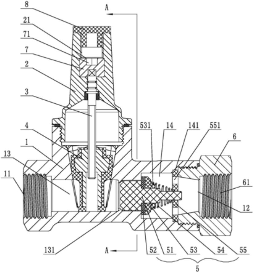
    1. A water meter protection valve, comprising a valve body, a valve cover, a valve rod, and a gate plate connected to the bottom end of the valve rod. The two ends of the valve body are respectively provided with an inlet end and an outlet end. The valve body is internally provided with a flowing water channel for medium circulation. The utility model is characterized in that: a cavity communicating with the flowing water channel is arranged on one side of the valve body opposite to the gate plate and located at the outlet end; the utility model further comprises a check mechanism, which comprises a valve core, a sealing ring, a pressure ring, a spring, and a positioning ring. The sealing ring, pressure ring, spring, and positioning ring are arranged in the cavity and sequentially sleeved on the valve core towards the outlet end. The outer circumferential wall of the valve core is provided with a convex ring located in the flowing water channel and abutting against the sealing ring. The sealing ring is located at the communication point between the flowing water channel and the cavity, and is used to control the communication and cutoff between the two. The two ends of the spring are respectively abutted against the pressure ring and the positioning ring. The positioning ring is provided with a through port communicating with the cavity. The valve core can reciprocate towards the positioning ring. The outlet end is provided with a connecting head threadedly connected thereto, and the connecting head is provided with a through hole communicating with the flowing water channel.

    2. A water meter protection valve according to claim 1, characterized in that a guide block is provided on the side of the convex ring facing the water inlet end.

    3. A water meter protection valve according to claim 2, characterized in that at least four guide blocks are provided, and are circumferentially arranged on the outer circumferential wall of the valve core.

    4. A water meter protection valve according to claim 3, characterized in that a protrusion is provided in the water flow channel on the side of the guide block facing the inlet end, which protrusion abuts against the guide block.

    5. A water meter protection valve according to claim 1, characterized in that the spring adopts a tower spring, and the end of the tower spring with a smaller inner diameter abuts against the end face of the positioning ring.

    6. A water meter protection valve according to claim 5, characterized in that a protrusion is provided on the end face facing the pressure ring, and the end of the tower spring with a larger inner diameter is sleeved on the protrusion.

    7. A water meter protection valve according to claim 1, characterized in that a limit slot adapted to the positioning ring is provided in the cavity.

    8. A water meter protection valve according to claim 1, characterized in that a groove is provided at the top of the valve cover, the top of the valve rod extends upward into the groove, and a lock block fitted over the top of the valve rod is provided in the groove, with a lock hole provided at the top of the lock block.

    9. A water meter protection valve according to claim 8, characterized in that the top of the valve cover is provided with a sealing cover that is threadedly connected to the groove.

    10. A water meter protection valve according to claim 1, characterized in that the valve body is made of ductile iron, and its inner and outer surfaces are sprayed with epoxy resin powder.

    11-11

    2025