Your location:

/ Valve products / ball valve / fully welded ball valve / Q61F Fully Welded Ball Valve
全国销售热线:0577-67378222

Product classification of Kaiweixi

KAI WEI XI CHAN PIN FEN LEI
  • Q61F Fully Welded Ball Valve

  • More fully welded ball valve>>

  • More ball valve>>

  • More valve>>

Contact Us
  • Phone:+86(577)6730 7899
  • Mobile:+86 189 6779 6135
  • Fax:+86(577)6738 7099
  • Email:Yannie@kaiweixi.com
  • Address:
  • Website:https://www.kaiweixi.com
Other valve products you may need
  • Q367F Fully Welded Ball Valve
Q61F Fully Welded Ball Valve

Q61F Fully Welded Ball Valve

  • Model:Q61F-16C/Q61F-25C/Q61F-40C
  • Specification:DN15~DN1200
  • Temperature:≤550℃
  • Medium:Water, oil, gas, and certain corrosive liquids
  • Pressure:PN16,PN25,PN40
  • Connection method:Welded
  • Driving method:Manual, worm gear, electric, pneumatic
  • Material:Carbon steel,stainless steel
x

Add QR code to serve you!

x

Add QR code to serve you!

x

Add QR code to serve you!

x
Q61F Fully Welded Ball ValveOverview

Q61F Fully Welded Ball Valve Overview

Q61F fully welded ball valve is a permanent cut-off valve with a valve body and pipeline connected by welding of the same material, without external flanges and bolt connection points. The valve body is formed by welding multiple forgings or steel plates through advanced technology, and the internal structure adopts floating or fixed ball structure and soft sealing valve seat such as polytetrafluoroethylene. This valve is designed for high temperature, high pressure, and harsh working conditions, and can be opened and closed by rotating the ball 90 degrees. It has extremely high structural strength and sealing integrity. Mainly used in urban gas backbone networks, long-distance oil and gas pipelines, regional heating systems, and other buried or important above ground pipelines that are not allowed to leak, as key cutoff equipment for the system.

Q61F Fully Welded Ball Valve Product Image

Q61F Fully Welded Ball ValveCharacteristic

Q61F Fully Welded Ball Valve Features

1. Fully welded leak free structure: The valve body is formed by integral welding without any detachable flange connections, fundamentally eliminating the risk of external leakage of the valve body, especially suitable for the transportation of flammable, explosive, and toxic media.

2. High strength and long life: The welded valve body structure is continuous, with uniform stress distribution, strong pressure bearing capacity, and resistance to pipeline stress deformation and seismic loads. The design life is usually consistent with the pipeline.

3. Direct burial and compact design: No need to build valve wells, can be directly buried underground, saving space and construction costs. The external structure is extremely compact, with only a short valve neck exposed to the ground for easy operation.

4. Extremely low maintenance requirements: The fully welded sealed structure does not require maintenance under normal working conditions and operates reliably. The valve stem usually adopts a dual seal and grease injection emergency seal design to further ensure long-term sealing.

5. High performance sealing and driving: The sealing pair can adapt to large pressure and temperature changes, and is often equipped with fire-resistant design. Reliable ground or remote operation can be achieved by extending the valve stem on the ground or directly connecting it to a fully welded actuator.

Q61F Fully Welded Ball Valvestructure principle

Q61F Fully Welded Ball Valve Structure Diagram

Parts Name Material List

NO.NameMaterial
1BodyA105
2BallA105+ENP
3sealing ringPPL
4packingflexible graphite
5StemF6A
6bleeder valveA105-Hzn


Q61F Fully Welded Ball Valvetechnology parameter
Performance Specification
Nominal Pressure1.6/2.5/4Mpa
Shell Test2.4/3.75/6
Seal Test1.76/2.75/4.4
Suitable Temp.≤500


Q61F Fully Welded Ball Valvestandard size

Dimensions Standard Requirements

1. The structural length of the valve shall conform to the standard GB/T 12221.

2. The connecting flange shall conform to the standard GB/T 12234.

Q61F Fully Welded Ball Valve View Drawing

Q61F Fully Welded Ball Valve Dimensions Table

DNL(RF)L(WE)D1D2H1(手柄)H1(涡轮)W(手柄)W(涡轮)
15150210274864-129-
20160230346076-159-
25180230427685-159-
32200260488995-245-
402303006089124-245-
5027030076114162-30-
6528030089140175-320-
80300325114168192169450-
100350325141203205183450230
125350350168219225203450230
1504004002192732452241000230
2005025212733512852621000320
2505685603254263483221500350
300648635377508-355-350


Articles related to technology research and development
  • Wafer-type ball valve patented

       The utility model provides a wafer-type float valve, which includes a valve body and a driving mechanism. The valve body is provided with a through medium channel in the axial direction, and is tubular in shape. It also includes a butterfly plate that fits and seals with the inner wall of the medium channel. The driving mechanism comprises a valve shaft that passes through the valve body and is connected to the butterfly plate, a valve rod connected to the outer end of the valve shaft in the radial direction, and a float ball connected to the valve rod. The valve rod is provided with a limit bolt that is threadedly connected to the valve body in the swinging direction. The butterfly plate can rotate relative to the valve body. The front end of the valve body at the inlet of the medium channel is provided with a filter screen, which is hollow and hemispherical in shape. The end face of the valve body opposite the filter screen is provided with an annular groove, and the open end of the filter screen is provided with a raised edge that is embedded in the annular groove. The utility model can filter the medium, is simple to install, time-saving, labor-saving, small in size, widely applicable, and can reduce the impact force of the medium on the butterfly plate.
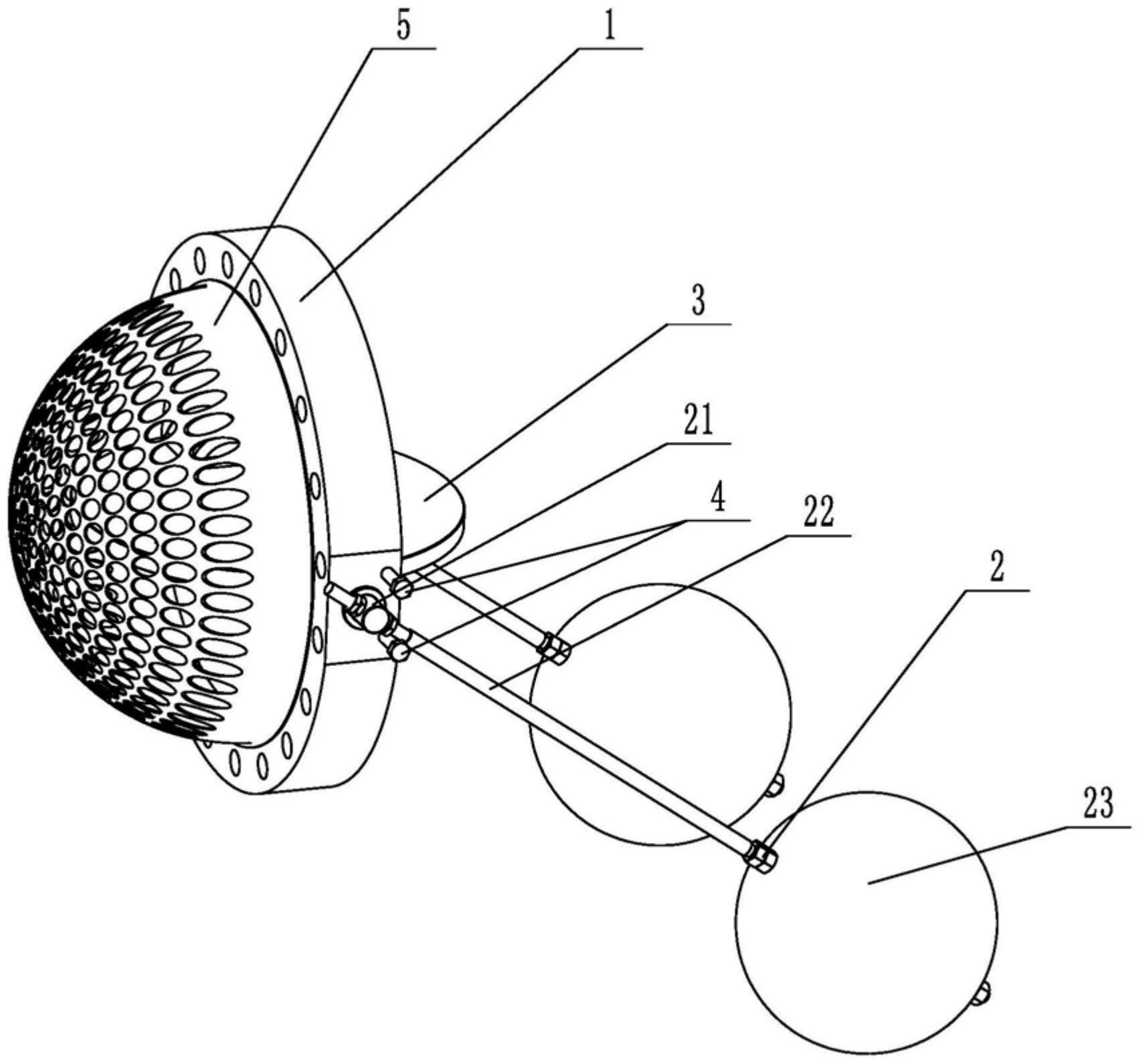
    1. A double-clip type float valve, comprising a valve body and a driving mechanism. The valve body is provided with a through medium channel in the axial direction. It is characterized in that the valve body is tubular and further comprises a butterfly plate that fits and seals with the inner wall of the medium channel. The driving mechanism comprises a valve shaft passing through the valve body and connected to the butterfly plate, a valve rod connected to the outer end of the valve shaft in the radial direction, and a float connected to the valve rod. The valve rod is provided with a limit bolt threadedly connected to the valve body in the swinging direction. The butterfly plate is rotatable relative to the valve body. The front end of the valve body located at the inlet of the medium channel is provided with a filter screen. The filter screen is hollow and hemispherical. The end surface of the valve body opposite the filter screen is provided with an annular groove. The open end of the filter screen is provided with a convex edge embedded in the annular groove.

    2. A wafer-type float valve according to claim 1, characterized in that the valve rod penetrates one end of the valve shaft located outside the valve body, and is threadedly engaged with the valve rod through a nut to clamp the valve shaft and achieve positioning of the valve rod.

    3. A wafer-type ball valve according to claim 2, characterized in that a step is provided at the position on the valve shaft connected to the valve body, a groove is provided at the position on the outer circumferential wall of the valve body corresponding to the step, and a gland is sleeved on the valve shaft, which is threadably connected to the groove and abuts against the step.

    4. A wafer-type ball valve according to claim 3, characterized in that a sealing groove is provided on the side of the groove facing the butterfly plate, and a sealing ring sleeved on the valve shaft is arranged in the sealing groove.

    5. A wafer-type ball valve according to claim 1, characterized in that an inner groove is provided on the side wall within the annular groove, and an elastic snap ring, which is used to press the convex edge and is compatible with the inner groove, is provided within the annular groove.

    6. A wafer-type ball valve according to claim 5, characterized in that the bottom of the convex edge is provided with a plurality of protrusions arranged around the center of the filter screen, and the annular groove is provided with a limiting groove adapted to the protrusions.

    7. A wafer-type float valve according to claim 6, characterized in that the protrusion is hemispherical. 8. A wafer-type float valve according to claim 7, characterized in that a clamping groove is provided at the junction of the protrusion and the protruding edge, and a clamping block adapted to the clamping groove is provided at the opening of the limiting groove.