Your location:

/ Valve products / check valve / Lift Check Valve / H41W Lift Check Valve
全国销售热线:0577-67378222

Product classification of Kaiweixi

KAI WEI XI CHAN PIN FEN LEI
  • H41W Lift Check Valve

  • More Lift Check Valve>>

  • More check valve>>

  • More valve>>

Contact Us
  • Phone:+86(577)6730 7899
  • Mobile:+86 189 6779 6135
  • Fax:+86(577)6738 7099
  • Email:Yannie@kaiweixi.com
  • Address:No. 1, Linxia Road, Sanqiao Industrial Zone, Oubei Street, Yongjia County, Zhejiang Province,china
  • Website:https://www.kaiweixi.com
Other valve products you may need
  • DRVZ Nozzle Check Valve
  • HC41X Muffler Check Valve
  • H12W Internal Thread Brass Lift Check Valve
  • H42W Vertical Check Valve
  • H71W Wafer Check Valve
H41W Lift Check Valve

H41W Lift Check Valve

  • Model:H41W-25I/H41W-40I/H41W-64I/H41W-10I/H41W-25P/H41W-40P/H41W-64P/H41W-10P/H41W-10C/H41W-25C/H41W-40C
  • Specification: DN15-200
  • Temperature:≤ 550 ℃
  • Medium:Water, Steam, Oil Products, Weakly Corrosive Media
  • Pressure:PN25,PN40,PN64
  • Connection method: Flange
  • Driving method:automated
  • Material:Stainless Steel,carbon steel,Cr-Mo-V Steel
x

Add QR code to serve you!

x

Add QR code to serve you!

x

Add QR code to serve you!

x
H41W Lift Check ValveOverview

H41W Lift Check Valve Overview  

The H41W Lift Check Valve is an automatic valve that utilizes flanged connections and operates through the vertical lifting and lowering motion of its disc to achieve unidirectional flow control. The valve body is typically constructed from materials such as cast steel, stainless steel, or cast iron, featuring a metal-sealed internal structure where the sealing surfaces of the disc and seat are often made of the base material or overlay-welded with alloy.Its working principle involves the disc being lifted open by the pressure of forward-flowing medium and automatically closing by rapidly returning to the seat under its own weight and reverse pressure when the medium stops or reverses.Designed specifically for horizontal pipelines, this valve offers a simple and reliable structure. It is suitable for pipeline systems handling media such as water, steam, and oil products, with nominal pressure ratings ranging from PN16 to PN160. Widely used in petroleum, chemical, power, water supply, and drainage industries, it serves as a fundamental safety device to prevent medium backflow.

H41W Lift Check Valve Product Image

H41W Lift Check ValveCharacteristic

H41W Lift Check Valve Features

1. Simple Structure and Reliable Operation  

  Adopting a classic lift-type design with minimal moving parts, this valve offers low failure rates. It operates through the combined action of disc weight and medium pressure, requiring no external power or complex controls.

2. Strict Installation Orientation Requirements  

  The valve must be installed horizontally with the valve stem axis strictly vertical. Correct installation orientation is the fundamental prerequisite for ensuring reliable sealing and proper operation.

3. Metal Sealing with High Temperature Resistance  

  The disc and seat feature a metal-to-metal hard-seal design, providing excellent resistance to high temperatures and wear. This makes it suitable for high-temperature media such as steam and hot oil, ensuring a long service life.

4. Rapid Closure and Low Flow Resistance  

  The short vertical travel of the disc enables fast and direct closure, effectively preventing medium backflow and mitigating water hammer effects. When fully open, the valve offers an unobstructed flow path with minimal pressure loss.

5. Easy Maintenance and Wide Applicability  

  With its robust construction, the valve requires minimal maintenance. If sealing surfaces wear over time, performance can often be restored through grinding, keeping maintenance costs low. It is suitable for a variety of non-highly corrosive industrial media.

H41W Lift Check Valvestructure principle

H41W Lift Check Valve Structure Diagram

Parts Name Material List

NO.NameMaterial
5boltChromium-Molybdenum-Vanadium Steel (Cr-Mo-V Steel), Stainless Steel
4discChromium-Molybdenum Steel (Cr-Mo Steel), Chromium-Nickel-Titanium Stainless Steel
3sealing surfaceHard Alloy
2gasketPTFE Spiral-Wound Metal-Asbestos Gasket
1bodyChromium-Molybdenum Steel (Cr-Mo Steel), Chromium-Nickel-Titanium Stainless Steel


H41W Lift Check Valvetechnology parameter
Performance Specification
Nominal Pressure2.5/4/6.4/10Mpa
Shell Test3.75/6/9.6/15
Seal Test2.75/4.4/7.04/11
Suitable Temp.≤550


H41W Lift Check Valvestandard size

Dimensions Standard Requirements

1. The structural length of the valve shall conform to the standard GB/T 12221.

2. The connecting flange shall conform to the standard GB/T 17241.6.

H14W Lift Check Valve View Drawing

H14W Lift Check Valve Dimension Table

N(㎜)尺寸(㎜)
LDD1D2bfZ-фdHD3
151309565451624-ф14100-
2015010575551624-ф14105-
2516011585651624-ф14115110
32190135100781824-ф18120120
40200145110851834-ф18140135
502301601251002034-ф18150150
652901801451202238-ф18160175
803101951601352238-ф18175200
1003502301901602438-ф23200230
1254002702201882838-ф25230273
1504803002502183038-ф25265330
20060036031027834312-ф25300365


Articles related to technology research and development
  • Slow-closing wafer check valve patent

       The utility model provides a slow-closing wafer check valve, which includes a valve body, a valve disc, a valve shaft, and a torsion spring sleeved on the valve shaft. The valve body is provided with a medium channel for medium circulation in the axial direction, which includes an inlet end and an outlet end. The valve disc, valve shaft, and torsion spring are symmetrically arranged in two groups relative to the center of the valve body. The utility model further includes a damping device located at the inlet end, which includes a cylinder inserted on the valve body, a piston rod located inside the cylinder, a spring, and a cover connected to the outer end of the cylinder. The cylinder is provided with a first cavity and a second cavity that are connected and communicated. The cross-section of the second cavity is square, and its cross-sectional area is larger than that of the first cavity. One end of the piston rod located inside the medium channel is provided with a movable block. The utility model has low noise and technical characteristics of quick opening, slow closing, and water hammer elimination, enabling light-load pump start-up and preventing the generation of water hammer during pump shutdown.
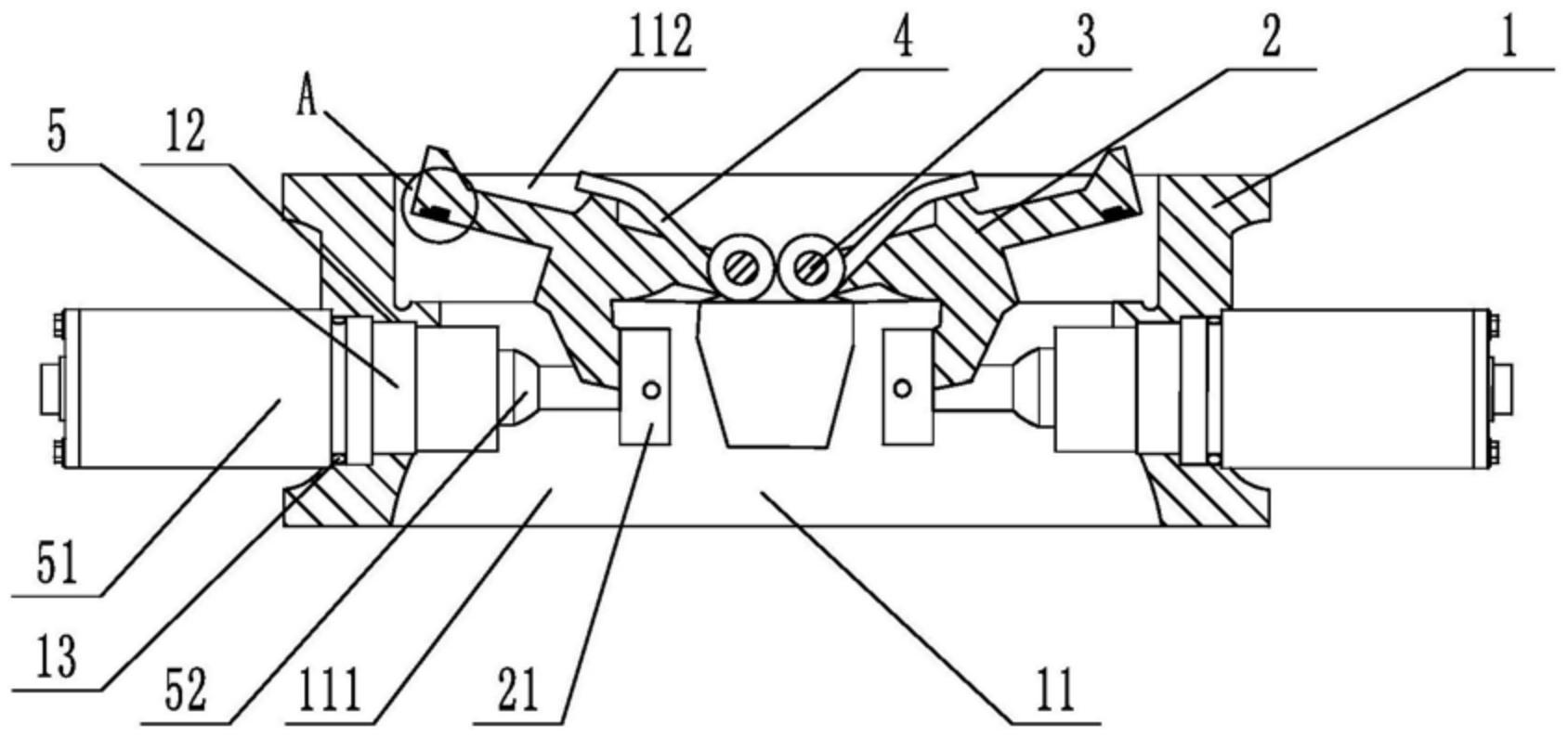
    1. A slow-closing wafer check valve, comprising a valve body, a valve disc, a valve shaft, and a torsion spring sleeved on the valve shaft. The valve body is provided with a medium passage for medium circulation in the axial direction, and the medium passage includes an inlet end and an outlet end. The valve disc, valve shaft, and torsion spring are symmetrically arranged in two groups relative to the center of the valve body. The valve also comprises a damping device located at the inlet end. The damping device includes a cylinder inserted on the valve body, a piston rod located inside the cylinder, a spring, and a cover connected to the outer end of the cylinder. The cylinder is provided with a first cavity and a second cavity that are connected and communicated. The cross-section of the second cavity is square, and the cross-sectional area of the second cavity is larger than that of the first cavity. One end of the piston rod is located inside the second cavity, and the other end penetrates through the first cavity and is located inside the medium passage. The end of the piston rod located inside the medium passage is provided with a movable block, and the end of the piston rod located inside the second cavity is provided with an external thread. The second cavity is provided with a limit plate that is adapted to and threadedly connected with the piston rod. The spring is sleeved on the piston rod, with one end abutting against the limit plate and the other end abutting against the inner wall of the second cavity. The side of the valve disc facing the piston rod is provided with a driving block that cooperates with the movable block. During the closing process of the valve disc, the side of the driving block facing the center of the valve body cooperates with the movable block to achieve displacement of the piston rod relative to the cylinder towards the center of the valve body. The damping device is symmetrically arranged in two groups relative to the center of the valve body.

    2. A slow-closing wafer check valve according to claim 1, characterized in that a square hole is axially provided at the end of the piston rod located in the second cavity, an adjuster is inserted at a position on the cover corresponding to the square hole, a driving rod adapted to the square hole is provided at the end of the adjuster, and the adjuster is rotatable relative to the cover.

    3. A slow-closing wafer check valve according to claim 2, characterized in that a limit slot is provided at the connection between the cover and the regulator, and a limit mechanism is arranged inside the limit slot. The limit mechanism comprises a ball, a tower spring connected to the ball, and a positioning column for fixing the tower spring. At least four engaging slots adapted to the ball are provided circumferentially at the connection between the regulator and the cover.

    4. A slow-closing wafer check valve according to claim 3, characterized in that the top edge of the engaging groove is provided with a rounded corner.

    5. A slow-closing wafer check valve according to claim 1, characterized in that the valve body is provided with a stepped groove adapted to the cylinder body.

    6. A slow-closing wafer check valve according to claim 5, characterized in that a sealing ring is sleeved at the connection between the cylinder and the valve body.

    7. A slow-closing wafer check valve according to claim 1, characterized in that the valve disc is provided with a build-up welding layer that is sealed with the valve body. 8. A slow-closing wafer check valve according to claim 7, characterized in that one side of the build-up welding layer is provided with vulcanized rubber that is sealed with the valve body.