Your location:

/ Valve products / ball valve / Eccentric Semi-ball Valve / DYP940F Electric Top-entry Semi-ball Valve
全国销售热线:0577-67378222

Product classification of Kaiweixi

KAI WEI XI CHAN PIN FEN LEI
  • DYP940F Electric Top-entry Semi-ball Valve

  • More Eccentric Semi-ball Valve>>

  • More ball valve>>

  • More valve>>

Contact Us
  • Phone:+86(577)6730 7899
  • Mobile:+86 189 6779 6135
  • Fax:+86(577)6738 7099
  • Email:Yannie@kaiweixi.com
  • Address:
  • Website:https://www.kaiweixi.com
Other valve products you may need
  • PQ340H Side-entry Semi-ball Valve
  • PQ640H Pneumatic Eccentric Semi-ball Valve
  • PQ940F Electric Eccentric Semi-ball Valve
  • PQ340Y Worm Gear Operated Eccentric Semi-ball Valve
  • PQ40F Manual Eccentric Semi-ball Valve
DYP940F Electric Top-entry Semi-ball Valve

DYP940F Electric Top-entry Semi-ball Valve

  • Model:DYP940F-6Q/DYP940F-10Q/DYP940F-16Q/DYP940F-6C/DYP940F-10C/DYP940F-16C/DYP940F-6P/DYP940F-10P/DYP940F-16P
  • Specification:DN50-DN2000
  • Temperature:-29~540℃
  • Medium:Water and similar media
  • Pressure:PN6,PN10,PN16
  • Connection method:flange
  • Driving method:electric
  • Material:Ductile Iron, Cast Steel, Stainless Steel
x

Add QR code to serve you!

x

Add QR code to serve you!

x

Add QR code to serve you!

x
DYP940F Electric Top-entry Semi-ball ValveOverview

The DYP940F Top-Entry Segment Ball Valve is an electrically driven eccentric hemispherical valve that adopts a top mounted structure. Its core feature is that all internal components of the valve (valve core, valve seat, valve stem) can be assembled, inspected, and maintained through the opening above the valve body, without the need to remove the valve from the pipeline. The valve is opened and closed by driving the eccentric hemispherical valve core to rotate 90 degrees through an integrated electric actuator. The "F" in the model usually represents that the valve seat is made of soft sealing material (such as reinforced polytetrafluoroethylene PTFE). The top-down design greatly simplifies online maintenance, making it particularly suitable for harsh working conditions with limited space, high requirements for maintenance convenience, or no interruption of processes. It is a key equipment in the fields of petroleum, chemical, natural gas, and long-distance pipelines that pursues high reliability and low maintenance costs.

Product Image:DYP940F Electric Top-entry Semi-ball Valve

DYP940F Electric Top-entry Semi-ball ValveCharacteristic

1. Unique online maintenance capability: Thanks to the top mounted structure, when internal seals need to be repaired or replaced, all internal components can be removed from above by simply opening the pressure seal cover or maintenance cover on the top of the valve body, without cutting or disassembling the pipeline. This greatly reduces maintenance downtime, workload, and costs.

2. Eccentric structure and soft seal design: Adopting an eccentric valve stem design ensures that the valve core instantly disengages from the valve seat during opening and closing, achieving frictionless operation and reducing operating torque. When closed, self wedging force is generated with the help of eccentricity, combined with the "F" type soft valve seat, which can achieve bubble level sealing and zero leakage, suitable for clean or tightly sealed media.

3. Electric Drive and Intelligent Control: Equipped with an integrated intelligent electric actuator that can receive control signals such as 4-20mA, enabling remote control, precise proportional adjustment, or switch operation. The actuator usually integrates overload protection, stroke control, and fieldbus interface, making it easy to connect to DCS/PLC systems.

4. Excellent flow and self-cleaning performance: When the valve is fully opened, the hemispherical valve core completely separates from the flow channel, forming a straight flow channel with extremely low flow resistance. During the opening and closing process, the scraping effect of the valve core edge can effectively remove the attachments on the sealing surface and has a certain self-cleaning ability.

5. High reliability and safety: The upper structure adopts a pressure self sealing valve cover, and the higher the pressure, the more reliable the sealing. Valves are usually specially designed for fire safety, anti-static, and other aspects. The main sealing components are modularized for quick replacement, ensuring long-term stable operation of the system.

DYP940F Electric Top-entry Semi-ball Valvestructure principle

Structural Drawing:DYP940F Electric Top-entry Semi-ball Valve

List of Component Names and Materials


Component NameMaterial
Valve BodyQT450, WCB, ZG20CrMo, ZG1Cr18Ni9Ti
Valve Stem2Cr13, 1Cr13
Valve DiscAlloy nitrided steel, Nitrided stainless steel, Wear-resistant steel
Valve SeatAlloy nitrided steel, Nitrided stainless steel, Wear-resistant steel
BearingAluminum bronze, FZ-1 composite material
PackingPTFE (Polytetrafluoroethylene), Flexible graphite


DYP940F Electric Top-entry Semi-ball Valvetechnology parameter

Performance Specification Sheet


Performance Specification Sheet
Nominal Pressure0.61.01.6MPa
Strength test pressure0.91.52.4
Sealing test pressure0.661.11.76
Applicable Temperature-29~540


DYP940F Electric Top-entry Semi-ball Valvestandard size


Standard requirements for external dimensions

1. The structural length of the valve shall comply with the standard of GB/T12221

2. Connecting flanges according to GB/T17241.6 standard

Outline Drawing:DYP940F Electric Top-entry Semi-ball Valve

Outline dimension table

Nominal pressureNominal diameterconnection size
LDKdbfz-d0HwHd
0.6MPa50180140110881624-φ14295350
802001901501241824-φ18310365
1002292101701441824-φ18330380
1252542402001741828-φ18345405
1502672652251992028-φ18370440
2002923202802542228-φ18405470
25033037533530924212-φ18480540
30039044039536324212-φ22520580
35043049044541324212-φ22570630
40053054049546324216-φ22630710
45058059555051824216-φ22690770
55066064560056826220-φ22740820
60084075570566730220-φ26840940
70090086081077226524-φ269601040
800100097592087826524-φ3010801180
90011001075102097826524-φ3011901280
1000120011751120107826528-φ3013101420
1100125012751220118028528-φ3013901480
1200130014051340129528532-φ3014201530
1400150016301560151032536-φ3615401650
1600180018301760171034540-φ3616601750
1800200020451970191836544-φ3917901860
2000220022652180212538548-φ4219201990

Nominal pressureNominal diameterconnection size
LDKdbfz-d0HwHd
1.0MPa50180160125991824-φ18295350
802002001601322028-φ18310365
1002292201801562228-φ18330380
1252542502101842228-φ18345405
1502672852402112428-φ22370440
2002923402952662428-φ22405470
25033039535031926212-φ22480540
30039044540037026212-φ22520580
35043050546042926216-φ22570630
40053056551548026216-φ26630710
45058061556553028220-φ26690770
50066067062058228220-φ26740820
60084078072568234220-φ30840940
70090089584079434524-φ309601040
8001000101595090136524-φ3310801180
900110011151050100138528-φ3311901280
1000120012301160111238528-φ3613101420
1100125013401270122242528-φ3613901480
1200130014551380132844532-φ3914201530
1400150016751590153048536-φ4215401650
1600180019151820175052540-φ4816601750
1800200021152020195056544-φ4817901860
2000220023252230215060548-φ4819201990


Articles related to technology research and development
  • Wafer-type ball valve patented

       The utility model provides a wafer-type float valve, which includes a valve body and a driving mechanism. The valve body is provided with a through medium channel in the axial direction, and is tubular in shape. It also includes a butterfly plate that fits and seals with the inner wall of the medium channel. The driving mechanism comprises a valve shaft that passes through the valve body and is connected to the butterfly plate, a valve rod connected to the outer end of the valve shaft in the radial direction, and a float ball connected to the valve rod. The valve rod is provided with a limit bolt that is threadedly connected to the valve body in the swinging direction. The butterfly plate can rotate relative to the valve body. The front end of the valve body at the inlet of the medium channel is provided with a filter screen, which is hollow and hemispherical in shape. The end face of the valve body opposite the filter screen is provided with an annular groove, and the open end of the filter screen is provided with a raised edge that is embedded in the annular groove. The utility model can filter the medium, is simple to install, time-saving, labor-saving, small in size, widely applicable, and can reduce the impact force of the medium on the butterfly plate.
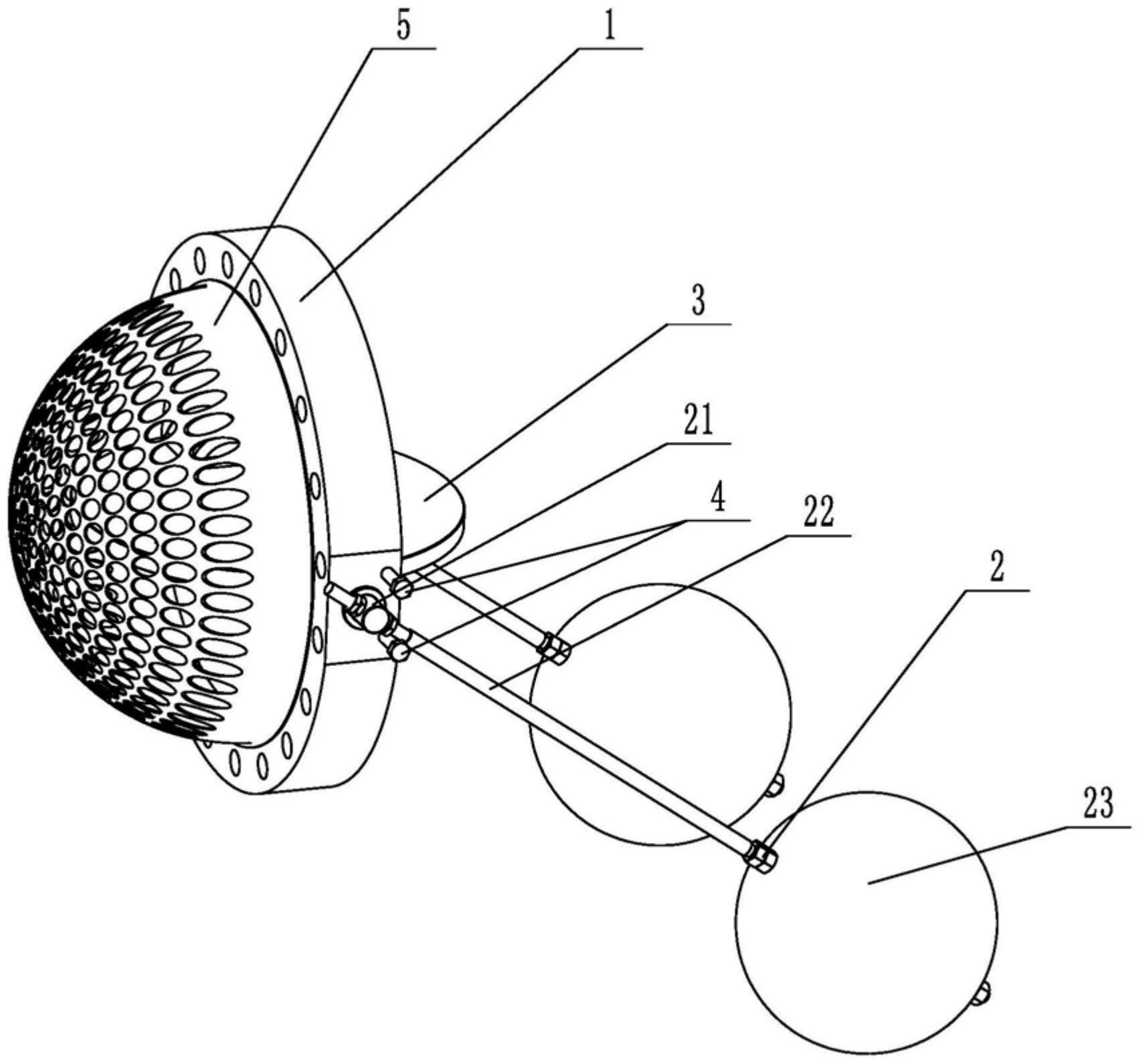
    1. A double-clip type float valve, comprising a valve body and a driving mechanism. The valve body is provided with a through medium channel in the axial direction. It is characterized in that the valve body is tubular and further comprises a butterfly plate that fits and seals with the inner wall of the medium channel. The driving mechanism comprises a valve shaft passing through the valve body and connected to the butterfly plate, a valve rod connected to the outer end of the valve shaft in the radial direction, and a float connected to the valve rod. The valve rod is provided with a limit bolt threadedly connected to the valve body in the swinging direction. The butterfly plate is rotatable relative to the valve body. The front end of the valve body located at the inlet of the medium channel is provided with a filter screen. The filter screen is hollow and hemispherical. The end surface of the valve body opposite the filter screen is provided with an annular groove. The open end of the filter screen is provided with a convex edge embedded in the annular groove.

    2. A wafer-type float valve according to claim 1, characterized in that the valve rod penetrates one end of the valve shaft located outside the valve body, and is threadedly engaged with the valve rod through a nut to clamp the valve shaft and achieve positioning of the valve rod.

    3. A wafer-type ball valve according to claim 2, characterized in that a step is provided at the position on the valve shaft connected to the valve body, a groove is provided at the position on the outer circumferential wall of the valve body corresponding to the step, and a gland is sleeved on the valve shaft, which is threadably connected to the groove and abuts against the step.

    4. A wafer-type ball valve according to claim 3, characterized in that a sealing groove is provided on the side of the groove facing the butterfly plate, and a sealing ring sleeved on the valve shaft is arranged in the sealing groove.

    5. A wafer-type ball valve according to claim 1, characterized in that an inner groove is provided on the side wall within the annular groove, and an elastic snap ring, which is used to press the convex edge and is compatible with the inner groove, is provided within the annular groove.

    6. A wafer-type ball valve according to claim 5, characterized in that the bottom of the convex edge is provided with a plurality of protrusions arranged around the center of the filter screen, and the annular groove is provided with a limiting groove adapted to the protrusions.

    7. A wafer-type float valve according to claim 6, characterized in that the protrusion is hemispherical. 8. A wafer-type float valve according to claim 7, characterized in that a clamping groove is provided at the junction of the protrusion and the protruding edge, and a clamping block adapted to the clamping groove is provided at the opening of the limiting groove.