Your location:

/ Valve products / check valve / Lift Check Valve / H71H Lift Type Wafer Check Valve
全国销售热线:0577-67378222

Product classification of Kaiweixi

KAI WEI XI CHAN PIN FEN LEI
  • H71H Lift Type Wafer Check Valve

  • More Lift Check Valve>>

  • More check valve>>

  • More valve>>

Contact Us
  • Phone:+86(577)6730 7899
  • Mobile:+86 189 6779 6135
  • Fax:+86(577)6738 7099
  • Email:Yannie@kaiweixi.com
  • Address:No. 1, Linxia Road, Sanqiao Industrial Zone, Oubei Street, Yongjia County, Zhejiang Province,china
  • Website:https://www.kaiweixi.com
Other valve products you may need
  • DRVZ Nozzle Check Valve
  • HC41X Muffler Check Valve
  • H12W Internal Thread Brass Lift Check Valve
  • H42W Vertical Check Valve
  • H71W Wafer Check Valve
H71H Lift Type Wafer Check Valve

H71H Lift Type Wafer Check Valve

  • Model:H71H-10C/H71H-16C/H71H-25C/H71H-40C/H71H-10P/H71H-16P/H71H-25P/H71H-40P
  • Specification:DN15-DN200
  • Temperature:≤ 425 ℃
  • Medium:Water, Steam, Oil
  • Pressure:PN10-PN40
  • Connection method:wafer
  • Driving method:automated
  • Material:WCB、Stainless Steel
x

Add QR code to serve you!

x

Add QR code to serve you!

x

Add QR code to serve you!

x
H71H Lift Type Wafer Check ValveOverview

H71H Wafer-Type Lift Check Valve Overview

The H71H wafer-type lift check valve is an energy-efficient check valve that adopts a single-disc lift-type design and operates automatically based on medium flow. It typically uses a wafer-type connection. The valve body is commonly made of stainless steel, cast steel, or ductile iron, with its internal single disc moving vertically along the centerline of the valve body. The valve can be installed horizontally or vertically. When the medium flows in the forward direction, it pushes the disc to open smoothly, providing an unobstructed flow path with low pressure loss. When the medium stops or flows in reverse, the disc quickly falls back and closes under the combined action of spring force and reverse medium pressure, ensuring reliable sealing and fast shut-off. This valve is specifically designed for pipeline systems with limited installation space and the need for quick closure. It is widely used in water supply and drainage, fire protection systems, HVAC, and industrial circulating water projects, serving as a simple, economical, and practical pipeline protection device.

H71H Lift Type Wafer Check Valve Product Image

H71H Lift Type Wafer Check ValveCharacteristic

H71H Wafer-Type Lift Check Valve Features

1. Simple structure with single-disc lift design: The single disc moves vertically along the centerline of the valve body, resulting in a small number of components, compact structure, low failure rate, economical manufacturing cost, and easy maintenance and replacement.

2. Space-saving wafer connection: The wafer-type connection provides a short valve body length, light weight, and small pipeline space occupation, making it especially suitable for applications with limited installation space.

3. Unobstructed flow path and low flow resistance: After opening, the disc completely clears the flow path, allowing the medium to pass through almost linearly, resulting in low fluid resistance and low pressure loss. Long-term operation can effectively reduce pumping energy consumption.

4. Flexible installation and strong adaptability: Can be installed horizontally or vertically (with medium flow from bottom to top). The spring-assisted closing ensures reliable sealing at various installation angles, offering a wide range of applications.

5. Quick closing and reliable sealing: The disc has a short lift stroke, and the spring-assisted return provides sensitive and rapid closing action, effectively reducing water hammer impact. The sealing performance is stable and reliable, protecting pipeline equipment safety.

H71H Lift Type Wafer Check Valvestructure principle

H71H Lift Type Wafer Check Valve Structure Diagram

Parts Name Material List

阀体Body阀瓣Disc阀座Body Seat阀瓣座Disc Seat弹簧Spring介质接触件Wetted Parts
A216WCB/A105A351 CF8410SS/StelliteSame as discInconelX-750410SS
A216WCB/A105A351 CF8VITON/BUNA/EPDMSame as discInconelX-750410 SS
A216WCB/A105A351CF8M316SS/StelliteSame as discInconelX-750316 SS
A216 WCB/A105A351 CF8MVITON/BUNA/EPDMSame as discInconelX-750316 SS
A352LCC/A350 LF2A351 CF8M316SS/StelliteSame as discInconelX-750316 SS
A352LCC/A350 LF2A351 CF8MVITON/BUNA/EPDMSame as discInconelX-750316SS
A351 CF8M/A182F316A351CF8MSame as bodySame as discInconelX-750316 SS
A351 CF8M/A182F316A351 CF8MVITON/BUNA/EPDMSame as discInconelX-750316 SS
A890GR 4A/A182F51A890 GR4ASame as bodySame as discInconelX-750A182F51
A890 GR5A/A182F53A890 GR 5ASame as bodySame as discInconelX-750A182F53
UNS S31254UNSS31254Same as bodySame as discInconelX-750254-SMO
UNSN26625UNSN26625Same as bodySame as discInconelX-750Inconel 625


H71H Lift Type Wafer Check Valvetechnology parameter
性能规范表Performance Specification
公称压力Nominal Pressure1.0-4Мpa
强度试验压力Shell Test1.5-6
密封试验压力Seal Test1.1-4.4
适用温度Suitable Temp.≤425


H71H Lift Type Wafer Check Valvestandard size

Dimensions Standard Requirements

1. The structural length of the valve shall conform to the standard ASME16.10.

2. The connecting flange shall conform to the standard ASME16.50.    

H71H Lift Type Wafer Check Valve View Drawing

H71H Lift Type Wafer Check Valve Dimensions Table

Pressure RatingDNDimensionsPipe FlangeWeight (kg)
LDdD1D2Dam of Bolts CircleNumber of BoltsDiameter of BoltsLength of Bolts
PN10 PN16 (长系列)152552152525654M12900.3
2031.562193030754M121000.45
2535.572243636854M121050.6
3240833143431004M161150.8
4045933952521104M161201.4
50561084862621254M161402.3
65631286275751458M161503.0
80711427690901608M161553.8
10080162951121121808M161705.0
1251101921101251322108M1620011
1501252181271501582408M2022516
PN102001602731652002082958M2026028
PN1620016027316520020829512M2026028

Wafer Type-PN25(Long Type)
Pressure RatingDNDimensionsPipe FlangeWeight (kg)
LDdD1D2Diam of Bolts CircleNumber of BollsDiameter of BoltsLength of Bolts
PN25 (长系列)152552152525654M12900.3
2031.562193030754M121000.45
2535.572243636854M121050.6
3240833143431004M161150.8
4045933952521104M161201.4
50561084862621254M161402.3
65631286275751458M161503.0
80711427690901608M161653.8
10080168951121121908M201805.2
1251101941101251322208M2422511.8
1501252241271501582508M2424518
20016028416520020831012M2428530

Wafer Type-PN40(Long Type)
Pressure RatingDNDimensionsPipe FlangeWeight (kg)
LDdD1D2Diam of Bolts CircleNumber of BoltsDiameter of BollsLength of Bolts
PN40 长系列)152552152525654M12900.3
2031.562193030754M121000.45
2535.572243636854M121050.6
3240833143431004M161150.8
4045933952521104M161201.4
50561084862621254M161402.3
65631286275751458M161503.0
80711427690901608M161653.8
10080168951121121908M201805.2
1251101941101251322208M2422513
1501252241271501582508M2424519
20016029116520020832012M2729532


Articles related to technology research and development
  • Slow-closing wafer check valve patent

       The utility model provides a slow-closing wafer check valve, which includes a valve body, a valve disc, a valve shaft, and a torsion spring sleeved on the valve shaft. The valve body is provided with a medium channel for medium circulation in the axial direction, which includes an inlet end and an outlet end. The valve disc, valve shaft, and torsion spring are symmetrically arranged in two groups relative to the center of the valve body. The utility model further includes a damping device located at the inlet end, which includes a cylinder inserted on the valve body, a piston rod located inside the cylinder, a spring, and a cover connected to the outer end of the cylinder. The cylinder is provided with a first cavity and a second cavity that are connected and communicated. The cross-section of the second cavity is square, and its cross-sectional area is larger than that of the first cavity. One end of the piston rod located inside the medium channel is provided with a movable block. The utility model has low noise and technical characteristics of quick opening, slow closing, and water hammer elimination, enabling light-load pump start-up and preventing the generation of water hammer during pump shutdown.
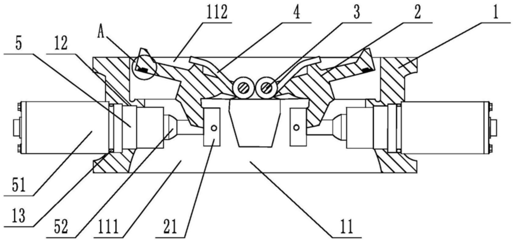
    1. A slow-closing wafer check valve, comprising a valve body, a valve disc, a valve shaft, and a torsion spring sleeved on the valve shaft. The valve body is provided with a medium passage for medium circulation in the axial direction, and the medium passage includes an inlet end and an outlet end. The valve disc, valve shaft, and torsion spring are symmetrically arranged in two groups relative to the center of the valve body. The valve also comprises a damping device located at the inlet end. The damping device includes a cylinder inserted on the valve body, a piston rod located inside the cylinder, a spring, and a cover connected to the outer end of the cylinder. The cylinder is provided with a first cavity and a second cavity that are connected and communicated. The cross-section of the second cavity is square, and the cross-sectional area of the second cavity is larger than that of the first cavity. One end of the piston rod is located inside the second cavity, and the other end penetrates through the first cavity and is located inside the medium passage. The end of the piston rod located inside the medium passage is provided with a movable block, and the end of the piston rod located inside the second cavity is provided with an external thread. The second cavity is provided with a limit plate that is adapted to and threadedly connected with the piston rod. The spring is sleeved on the piston rod, with one end abutting against the limit plate and the other end abutting against the inner wall of the second cavity. The side of the valve disc facing the piston rod is provided with a driving block that cooperates with the movable block. During the closing process of the valve disc, the side of the driving block facing the center of the valve body cooperates with the movable block to achieve displacement of the piston rod relative to the cylinder towards the center of the valve body. The damping device is symmetrically arranged in two groups relative to the center of the valve body.

    2. A slow-closing wafer check valve according to claim 1, characterized in that a square hole is axially provided at the end of the piston rod located in the second cavity, an adjuster is inserted at a position on the cover corresponding to the square hole, a driving rod adapted to the square hole is provided at the end of the adjuster, and the adjuster is rotatable relative to the cover.

    3. A slow-closing wafer check valve according to claim 2, characterized in that a limit slot is provided at the connection between the cover and the regulator, and a limit mechanism is arranged inside the limit slot. The limit mechanism comprises a ball, a tower spring connected to the ball, and a positioning column for fixing the tower spring. At least four engaging slots adapted to the ball are provided circumferentially at the connection between the regulator and the cover.

    4. A slow-closing wafer check valve according to claim 3, characterized in that the top edge of the engaging groove is provided with a rounded corner.

    5. A slow-closing wafer check valve according to claim 1, characterized in that the valve body is provided with a stepped groove adapted to the cylinder body.

    6. A slow-closing wafer check valve according to claim 5, characterized in that a sealing ring is sleeved at the connection between the cylinder and the valve body.

    7. A slow-closing wafer check valve according to claim 1, characterized in that the valve disc is provided with a build-up welding layer that is sealed with the valve body. 8. A slow-closing wafer check valve according to claim 7, characterized in that one side of the build-up welding layer is provided with vulcanized rubber that is sealed with the valve body.