Your location:

/ Valve products / ball valve / Fixed Ball Valve / Q347Y Turbine Fixed Ball Valve
全国销售热线:0577-67378222

Product classification of Kaiweixi

KAI WEI XI CHAN PIN FEN LEI
  • Q347Y Turbine Fixed Ball Valve

  • More Fixed Ball Valve>>

  • More ball valve>>

  • More valve>>

Contact Us
  • Phone:+86(577)6730 7899
  • Mobile:+86 189 6779 6135
  • Fax:+86(577)6738 7099
  • Email:Yannie@kaiweixi.com
  • Address:
  • Website:https://www.kaiweixi.com
Other valve products you may need
  • DQ347H Cryogenic Ball Valve
  • Q347H Top-Entry Flanged Ball Valve
  • Q47H Forged Steel Fixed Ball Valve
Q347Y Turbine Fixed Ball Valve

Q347Y Turbine Fixed Ball Valve

  • Model:Q347Y-16R/Q347Y-25R/Q347Y-40R/Q347Y-16/Q347Y-40P/Q347Y-100P/Q347Y-16C/Q347Y-25C/Q347Y100C
  • Specification:DN50-DN500
  • Temperature:≤425℃
  • Medium:Water, steam, oil and corrosive media
  • Pressure:PN16,PN25,PN40,PN100
  • Connection method:Flange
  • Driving method:Manual, worm gear, electric, pneumatic
  • Material:Carbon steel, stainless steel
x

Add QR code to serve you!

x

Add QR code to serve you!

x

Add QR code to serve you!

x
Q347Y Turbine Fixed Ball ValveOverview

Q347Y Turbine Fixed Ball Valve Overview

Q347Y turbine fixed ball valve is a fixed ball valve driven by a turbine transmission mechanism. Its sphere is fixed and supported by upper and lower rotating shafts, and does not produce floating displacement under high pressure. The valve seat usually adopts a metal hard seal or composite seal structure. The valve achieves high torque output through turbine gearbox deceleration transmission, making opening and closing operations effortless and precise. This design is suitable for high-pressure, large-diameter, and frequently operated pipeline systems in fields such as petroleum, natural gas, chemical, and power stations. It can reliably cut off and control water, steam, oil, and corrosive media, especially in situations where power actuators cannot be equipped.

Q347Y Turbine Fixed Ball Valve Product Image

Q347Y Turbine Fixed Ball ValveCharacteristic

Q347Y Turbine Fixed Ball Valve Features

1. Turbo transmission is labor-saving and precise: using a turbo worm gear reduction mechanism, it has a large output torque, easy operation, smooth transmission, and can achieve precise control and self-locking of valve opening and closing positions.

2. Fixed ball structure resistant to high pressure: The ball is fixed by bearings, with low rotational friction. The valve seat is not easily overloaded or deformed under medium pressure, ensuring that the valve can still open and close flexibly and maintain long-term sealing under high pressure differential conditions.

3. Double sealing and fire safety: A spring preloaded valve seat design is usually used to achieve bidirectional sealing. The sealing pair can be in the form of metal to metal or soft hard composite, and comply with fire safety standards.

4. Low flow resistance and high flow capacity: The full bore design brings minimal fluid resistance, making it suitable for long-term fully open operation of conveying pipelines and reducing energy consumption. The valve stem seal is reliable, and the anti blowing design has high safety.

5. Strong adaptability and easy maintenance: suitable for manual, semi-automatic or as a backup drive device. Partial structure supports online maintenance and valve seat sealing grease injection, extending service life and reducing maintenance costs.

Q347Y Turbine Fixed Ball Valvestructure principle

Q347Y Turbine Fixed Ball Valve Structures Diagram

Parts Name Material List

NO.NameMaterial
1BodyCarbon steel, stainless steel
2Ballstainless steel
3sealing ringrubber
4packingPTFE
5Stem2Cr13、stainless steel


Q347Y Turbine Fixed Ball Valvetechnology parameter
性能规范表Performance Specification
公称压力Nominal Pressure1.6-10Mpa
强度试验压力Shell Test2.4-15
密封试验压力Seal Test1.76-11
适用温度Suitable Temp.≤425


Q347Y Turbine Fixed Ball Valvestandard size

Dimensions Standard Requirements

1. The structural length of the valve shall conform to the standard ASME16.10.

2. The connecting flange shall conform to the standard ASME16.50.

Q347Y Turbine Fixed Ball Valve View Drawing

Q347Y Turbine Fixed Ball Valve Dimensions Table

公称通径主要外形尺寸和连接尺寸
LDD1D2bZ-dHH1D0
50178160125100164-1816085-
65191180145120184-1817095-
80206195160135208-18200110-
100229215180155208-18210120-
125356245210185228-18350215-
150394280240210248-23530190-
2004573352952652612-23575230600
2505334053553203012-25585260600
3006104604103753012-25730300600
3506865204704353416-25860350800
4007625805254853616-30935395800
4508646405855454020-30975440800
5009127056506084420-341060485800


Articles related to technology research and development
  • Wafer-type ball valve patented

       The utility model provides a wafer-type float valve, which includes a valve body and a driving mechanism. The valve body is provided with a through medium channel in the axial direction, and is tubular in shape. It also includes a butterfly plate that fits and seals with the inner wall of the medium channel. The driving mechanism comprises a valve shaft that passes through the valve body and is connected to the butterfly plate, a valve rod connected to the outer end of the valve shaft in the radial direction, and a float ball connected to the valve rod. The valve rod is provided with a limit bolt that is threadedly connected to the valve body in the swinging direction. The butterfly plate can rotate relative to the valve body. The front end of the valve body at the inlet of the medium channel is provided with a filter screen, which is hollow and hemispherical in shape. The end face of the valve body opposite the filter screen is provided with an annular groove, and the open end of the filter screen is provided with a raised edge that is embedded in the annular groove. The utility model can filter the medium, is simple to install, time-saving, labor-saving, small in size, widely applicable, and can reduce the impact force of the medium on the butterfly plate.
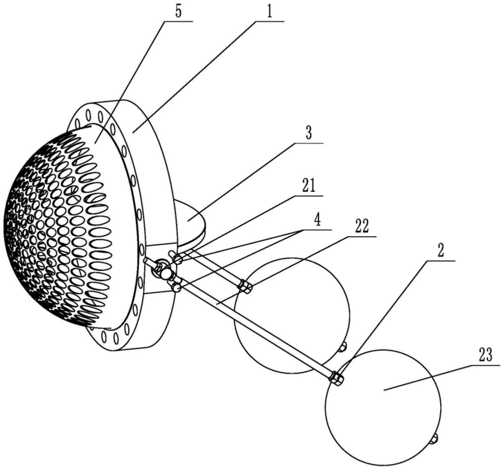
    1. A double-clip type float valve, comprising a valve body and a driving mechanism. The valve body is provided with a through medium channel in the axial direction. It is characterized in that the valve body is tubular and further comprises a butterfly plate that fits and seals with the inner wall of the medium channel. The driving mechanism comprises a valve shaft passing through the valve body and connected to the butterfly plate, a valve rod connected to the outer end of the valve shaft in the radial direction, and a float connected to the valve rod. The valve rod is provided with a limit bolt threadedly connected to the valve body in the swinging direction. The butterfly plate is rotatable relative to the valve body. The front end of the valve body located at the inlet of the medium channel is provided with a filter screen. The filter screen is hollow and hemispherical. The end surface of the valve body opposite the filter screen is provided with an annular groove. The open end of the filter screen is provided with a convex edge embedded in the annular groove.

    2. A wafer-type float valve according to claim 1, characterized in that the valve rod penetrates one end of the valve shaft located outside the valve body, and is threadedly engaged with the valve rod through a nut to clamp the valve shaft and achieve positioning of the valve rod.

    3. A wafer-type ball valve according to claim 2, characterized in that a step is provided at the position on the valve shaft connected to the valve body, a groove is provided at the position on the outer circumferential wall of the valve body corresponding to the step, and a gland is sleeved on the valve shaft, which is threadably connected to the groove and abuts against the step.

    4. A wafer-type ball valve according to claim 3, characterized in that a sealing groove is provided on the side of the groove facing the butterfly plate, and a sealing ring sleeved on the valve shaft is arranged in the sealing groove.

    5. A wafer-type ball valve according to claim 1, characterized in that an inner groove is provided on the side wall within the annular groove, and an elastic snap ring, which is used to press the convex edge and is compatible with the inner groove, is provided within the annular groove.

    6. A wafer-type ball valve according to claim 5, characterized in that the bottom of the convex edge is provided with a plurality of protrusions arranged around the center of the filter screen, and the annular groove is provided with a limiting groove adapted to the protrusions.

    7. A wafer-type float valve according to claim 6, characterized in that the protrusion is hemispherical. 8. A wafer-type float valve according to claim 7, characterized in that a clamping groove is provided at the junction of the protrusion and the protruding edge, and a clamping block adapted to the clamping groove is provided at the opening of the limiting groove.