Your location:

/ Valve products / ball valve / Fixed Ball Valve / Q347H Top-Entry Flanged Ball Valve
全国销售热线:0577-67378222

Product classification of Kaiweixi

KAI WEI XI CHAN PIN FEN LEI
  • Q347H Top-Entry Flanged Ball Valve

  • More Fixed Ball Valve>>

  • More ball valve>>

  • More valve>>

Contact Us
  • Phone:+86(577)6730 7899
  • Mobile:+86 189 6779 6135
  • Fax:+86(577)6738 7099
  • Email:Yannie@kaiweixi.com
  • Address:
  • Website:https://www.kaiweixi.com
Other valve products you may need
  • Q347Y Turbine Fixed Ball Valve
  • DQ347H Cryogenic Ball Valve
  • Q47H Forged Steel Fixed Ball Valve
Q347H Top-Entry Flanged Ball Valve

Q347H Top-Entry Flanged Ball Valve

  • Model:Q347H-16C/Q347H-25C/Q347H-40C/Q347H-64C/Q347H-16P/Q347H-25P/Q347H-40P/Q347H-64P
  • Specification:DN25-DN1200
  • Temperature:≤550℃
  • Medium:Water、Gas、 Oil
  • Pressure:PN16-PN320
  • Connection method:flange
  • Driving method:Manual, pneumatic, electric
  • Material:cast steel, stainless steel,alloy steel,Aluminum Nickel Bronze
x

Add QR code to serve you!

x

Add QR code to serve you!

x

Add QR code to serve you!

x
Q347H Top-Entry Flanged Ball ValveOverview

the Q347H Top-Entry Flanged Ball Valve Overview

The Q347H Top-Entry Flanged Ball Valve is a high-performance, trunnion-mounted ball valve designed with a top-entry configuration and flanged connections. Its key feature is an integral body structure, where the bonnet is bolted to the body from the top. This design allows for the complete assembly or removal of core components such as the ball, stem, and seats through the top opening without the need to remove the valve from the pipeline. Equipped with a metal hard-sealed structure, the valve is specifically engineered for high-temperature, high-pressure, and demanding media applications. It is suitable for critical systems in oil, natural gas, chemical, and long-distance pipeline industries, serving as essential equipment for reliable shut-off and efficient online maintenance.

Q347H Top-Entry Flanged Ball Valve Product Image

Q347H Top-Entry Flanged Ball ValveCharacteristic

the Q347H Top-Entry Flanged Ball Valve Features

1. Convenient online maintenance with top-entry design: The unique top-loading design allows for rapid inspection, replacement, or repair of internal core components while the valve remains in the pipeline, significantly reducing maintenance downtime and operational costs.

2. Reliable high-pressure sealing with integral valve body: The integral valve body structure eliminates the risk of cavity leakage. Combined with metal hard-sealed pairs (e.g., hard-faced with wear-resistant alloys), it ensures bidirectional zero-leakage sealing under high differential pressures and elevated temperatures.

3. Suitable for demanding conditions: Specifically designed for high temperatures, high pressures, and media containing particles or corrosive substances. The trunnion-mounted ball structure, paired with high-performance bearings, ensures stable operating torque and extended service life.

4. Fire-safe and safety design: Typically complies with fire safety standards such as API 607/API 6FA. In the event of soft seal failure, a secondary metal-to-metal seal is established. The stem features anti-blowout and anti-static designs.

5. Versatile and flexible operation modes: Can be equipped with various actuation options, including manual, gear, electric, or pneumatic drives, to meet diverse automation control requirements.


Q347H Top-Entry Flanged Ball Valvestructure principle

Q347H Top-Entry Flanged Ball Valve Structure Diagram

Parts Name Material List

NO.NameMaterial
1bodycast steel, stainless steel
2ballcast steel, stainless steel
3seal gasketPTFE
4packingPTFE
5Stemcast steel, stainless steel


Q347H Top-Entry Flanged Ball Valvetechnology parameter
Performance Specification
Nominal Pressure1.6-32Mpa
Shell Test2.4-48
Seal Test1.76-35.2
Suitable Temp.550


Q347H Top-Entry Flanged Ball Valvestandard size

Dimensions Standard Requirements

1. The structural length of the valve shall conform to the standard GB/T12221.

2. The connecting flange shall conform to the standard GB9113.

Q347H Top-Entry Flanged Ball Valve View Drawing

Q347H Top-Entry Flanged Ball Valve Dimensions Table

压力级主要尺寸公称通径
253240506580100125150200250300350400450500
PN1.6MPaL160180200230290310350400480600730850980110012001250
H240260307360410483512543581617672723758791828870
Kg9.6161928304155781152152703855028769801240
PN2.5MPaL160180200230290310350400480600730850980110012001250
H260280320360430490525567604642695742781815864905
Kg9.51619283045598212123028940254091311201280
PN4.0MPaL160180200230290310350400480600730850980110012001250
H260280320360436492527607649701750750790832875910
Kg101720253245598211523029540254091311241348
PN6.4MPaL160180200230290310350400480600730850980110012001250
H280320329365450509541663725781790806821858--
Kg101720253252681061682813554986891134--
150LbL127140165178190203229356394457533610686762864914
300LbL165178190216241283305381403502568648762838914991
600LbL21622924129233035643250855966078783888999110921194


Articles related to technology research and development
  • Wafer-type ball valve patented

       The utility model provides a wafer-type float valve, which includes a valve body and a driving mechanism. The valve body is provided with a through medium channel in the axial direction, and is tubular in shape. It also includes a butterfly plate that fits and seals with the inner wall of the medium channel. The driving mechanism comprises a valve shaft that passes through the valve body and is connected to the butterfly plate, a valve rod connected to the outer end of the valve shaft in the radial direction, and a float ball connected to the valve rod. The valve rod is provided with a limit bolt that is threadedly connected to the valve body in the swinging direction. The butterfly plate can rotate relative to the valve body. The front end of the valve body at the inlet of the medium channel is provided with a filter screen, which is hollow and hemispherical in shape. The end face of the valve body opposite the filter screen is provided with an annular groove, and the open end of the filter screen is provided with a raised edge that is embedded in the annular groove. The utility model can filter the medium, is simple to install, time-saving, labor-saving, small in size, widely applicable, and can reduce the impact force of the medium on the butterfly plate.
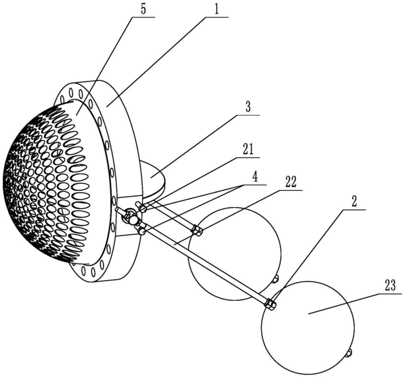
    1. A double-clip type float valve, comprising a valve body and a driving mechanism. The valve body is provided with a through medium channel in the axial direction. It is characterized in that the valve body is tubular and further comprises a butterfly plate that fits and seals with the inner wall of the medium channel. The driving mechanism comprises a valve shaft passing through the valve body and connected to the butterfly plate, a valve rod connected to the outer end of the valve shaft in the radial direction, and a float connected to the valve rod. The valve rod is provided with a limit bolt threadedly connected to the valve body in the swinging direction. The butterfly plate is rotatable relative to the valve body. The front end of the valve body located at the inlet of the medium channel is provided with a filter screen. The filter screen is hollow and hemispherical. The end surface of the valve body opposite the filter screen is provided with an annular groove. The open end of the filter screen is provided with a convex edge embedded in the annular groove.

    2. A wafer-type float valve according to claim 1, characterized in that the valve rod penetrates one end of the valve shaft located outside the valve body, and is threadedly engaged with the valve rod through a nut to clamp the valve shaft and achieve positioning of the valve rod.

    3. A wafer-type ball valve according to claim 2, characterized in that a step is provided at the position on the valve shaft connected to the valve body, a groove is provided at the position on the outer circumferential wall of the valve body corresponding to the step, and a gland is sleeved on the valve shaft, which is threadably connected to the groove and abuts against the step.

    4. A wafer-type ball valve according to claim 3, characterized in that a sealing groove is provided on the side of the groove facing the butterfly plate, and a sealing ring sleeved on the valve shaft is arranged in the sealing groove.

    5. A wafer-type ball valve according to claim 1, characterized in that an inner groove is provided on the side wall within the annular groove, and an elastic snap ring, which is used to press the convex edge and is compatible with the inner groove, is provided within the annular groove.

    6. A wafer-type ball valve according to claim 5, characterized in that the bottom of the convex edge is provided with a plurality of protrusions arranged around the center of the filter screen, and the annular groove is provided with a limiting groove adapted to the protrusions.

    7. A wafer-type float valve according to claim 6, characterized in that the protrusion is hemispherical. 8. A wafer-type float valve according to claim 7, characterized in that a clamping groove is provided at the junction of the protrusion and the protruding edge, and a clamping block adapted to the clamping groove is provided at the opening of the limiting groove.