Working Principle and Application
When used as a pressure relief valve, the main valve is installed in the drainage bypass, i.e., in parallel with the main pipeline. When the upstream pressure gradually rises above the set value of pilot valve 13, the main valve opens quickly to drain water and reduce pressure. It only closes slowly and smoothly when the upstream pressure drops below the set value of pilot valve 13, avoiding water hammer and ensuring the safety of the pipeline. When functioning as a pressure relief valve, it is mainly used to eliminate excessively high pressure that gradually increases due to supply exceeding demand, such as in the initial stage of fire fighting in fire hydrant systems, automatic sprinkler systems, and at the outlet of water pumps in various water supply systems. When used as a pressure relief valve, ball valve 12 is normally open.
When used as a pressure retaining valve, the main valve is installed on the main pipeline, i.e., in series with the main pipeline. The main valve remains closed as long as the water supply pressure upstream of the main valve is lower than the set value of pilot valve 13. It will automatically open to supply water to the downstream when the upstream pressure exceeds the set value of pilot valve 13, thus ensuring the water supply pressure upstream of the main valve. It is mainly used to maintain the minimum water supply pressure of urban main pipes. Especially in case of fire, it can prevent branch users from excessive water pumping which would reduce the pressure. When used as a pressure retaining valve, ball valve 12 is normally closed or replaced with a pipe plug.
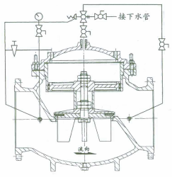
Structure diagram of 500X piston type pressure relief/holding valve
The valve consists of a main valve, pilot valve, needle valve, ball valve, pressure gauge, etc. It is categorized into diaphragm-type and piston-type based on different pipe diameters. Since the pilot valve, needle valve, ball valve, pressure gauge, etc., are connected to the main valve via conduits, they are collectively referred to as the conduit control system.
Main Parts and Materials
| 编号Serial Number | 零件名称Part Name | 材 质Material | | 编号Serial Number | 零件名称Part Name | 材 质Material |
| 1 | 阀 体Valve Body | 铸铁、不锈钢Cast Iron,Stainless Steel, | 10 | 压缩弹簧Compression Spring | 不锈钢Stainless Steel |
| 2 | 阀 座Valve Seat | 铜、不锈钢Copper, Stainless Steel | 11 | 阀 杆Valve Stem | 不锈钢Stainless Steel |
| 3 | 密封垫Gasket | 强化橡胶Reinforced Rubber | 12 | 球 阀Ball Valve | 铜Copper |
| 4 | 密封垫压板Gasket Pressure Plate | 铜、不锈钢Copper, Stainless Steel | 13 | 导 阀Pilot Valve | 铜Copper |
| 5 | 阀 盘Valve Disc | 铜、不锈钢Copper, Stainless Steel | 14 | 球 阀Ball Valve | 铜Copper |
| 6 | 膜 片Diaphragm | 强化橡胶Reinforced Rubber | 15 | 压力表Pressure Gauge | |
| 7 | 膜片压板Diaphragm Pressure Plate | 铜、不锈钢Copper, Stainless Steel | 16 | 球 阀Ball Valve | 铜Copper |
| 8 | 阀 盖Bonnet | 铸铁、不锈钢Cast Iron,Stainless Steel | 17 | 针 阀Needle Valve | 铜Copper |
| 9 | 球 阀Ball Valve | 青 铜Bronze | 18 | 微型过滤器Microfilter | 不锈钢Stainless Steel |