Your location:

/ Valve products / control valve / Electric Control Valve / D971X Electric Rubber-Lined Butterfly Valve
全国销售热线:0577-67378222

Product classification of Kaiweixi

KAI WEI XI CHAN PIN FEN LEI
  • D971X Electric Rubber-Lined Butterfly Valve

  • More Electric Control Valve>>

  • More control valve>>

  • More valve>>

Contact Us
  • Phone:+86(577)6730 7899
  • Mobile:+86 195 1816 9569
  • Fax:+86(577)6738 7099
  • Email:Lucas@kaiweixi.com
  • Address:No. 1, Linxia Road, Oubei Street, Yongjia County, Wenzhou City, Zhejiang Province,china
  • Website:https://www.kaiweixi.com
Other valve products you may need
  • ZAZP Electric Straight-through Single-seated Regulating Valve
  • ZS Series Zero Differential Pressure Start Solenoid Valve
  • ZSQ Electric Three-way Modulating Ball Valve
  • 700X Pump Control Valve
  • ZJM Electric Multi-stage Pressure-reducing Cage Guided Control Valve
D971X  Electric Rubber-Lined Butterfly Valve

D971X Electric Rubber-Lined Butterfly Valve

  • Model:D971X-10/D971X-16/D971X-10Q/D971X-16Q/D971X-10P/D971X-16P
  • Specification:DN50~1000
  • Temperature:-40~150℃
  • Medium:Air, water, sewage, oil, corrosive media, etc.
  • Pressure:PN1.0~1.6MPa
  • Connection method:Flange
  • Driving method:Electric
  • Material:Cast Iron,Ductile Iron,Stainless Steel
x

Add QR code to serve you!

x

Add QR code to serve you!

x

Add QR code to serve you!

x
D971X Electric Rubber-Lined Butterfly ValveOverview

D971X electric rubber-lined butterfly valve is an industrial automation execution unit consisting of a high-performance intelligent electric actuator and a center-line rubber-lined valve body. By receiving standard 4-20mA DC analog signals or switch signals from control systems, the actuator provides torque to drive the disc, rotating it within a 0-90 degree range. This adjusts the fluid flow area or achieves tight shut-off in real-time. The body cavity and disc sealing surfaces are fully lined with high-quality elastomers (e.g., EPDM, NBR), providing excellent corrosion and wear resistance while ensuring bi-directional bubble-tight zero leakage at low torque. Due to its compact structure, high flow capacity, and cost-effectiveness, the D971X series is widely used in water supply, sewage treatment, environmental protection, and general industrial fluid control networks.
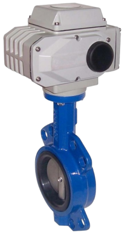
Product Image of D971X Electric Rubber-Lined Butterfly Valve

D971X Electric Rubber-Lined Butterfly ValveCharacteristic

1. Superior zero-leakage performance:The full-lined body structure creates an interference fit between the disc and the seat. The elastic compensation of the rubber ensures bi-directional bubble-tight sealing in the closed position, meeting ANSI Class VI standards.
2.Intelligent integrated electric drive:Equipped with an intelligent electronic actuator with a built-in servo system. It supports standard control signals, position feedback, overload protection, stall alarms, and fail-safe signal interruption logic.
3.Excellent corrosion and wear resistance:Different rubber linings can be configured based on the medium to isolate the fluid from the metal body. It is highly resistant to weak acids, alkalis, salts, and fluids with minor particulates.
4.Minimal flow resistance and high efficiency:The disc features a streamlined, ultra-thin design. When fully open, the flow path is nearly straight with an extremely low resistance coefficient, providing a large flow coefficient (Kv) and reducing pumping energy costs.
5.Compact and lightweight design:The wafer connection design significantly shortens the face-to-face length. Its small size and light weight save installation space and reduce mechanical loads on the pipeline and its supports.
6.Smooth operation and agile response:The actuator provides stable torque output. Combined with low-friction bearings, the disc responds rapidly and positions accurately even under high-frequency regulation conditions.
7.Intrinsic safety and protection:Driven by electricity, eliminating the need for complex air supply systems. It can be configured with fail-in-place or backup power reset functions to ensure process safety during power failures.
8.Modular design for easy maintenance:The simple structure has minimal wearing parts. Standardized actuator-to-body interfaces allow for online inspection or replacement of the actuator without removing the valve from the line.

D971X Electric Rubber-Lined Butterfly Valvestructure principle

Structural Drawing of D971X Electric Rubber-Lined Butterfly Valve


List of Component Names and Materials

Component NameMain Materials
Valve Body, BaseCast Iron,Ductile Iron,Stainless Steel
Butterfly Plate (Disc)Grey Cast Iron, Ductile Iron, Cast Steel, Stainless Steel and Special Materials
Sealing RingVarious Rubbers, PTFE (Teflon)
Valve Stem2Cr13 (AISI 420), Stainless Steel
PackingV-type PTFE Packing, Flexible Graphite Packing


D971X Electric Rubber-Lined Butterfly Valvetechnology parameter

Performance Specification Sheet

Performance Specification Sheet
Nominal Pressure1.01.6MPa
Strength test pressure1.52.4
Sealing test pressure1.11.76
Applicable Temperature-40~150


D971X Electric Rubber-Lined Butterfly Valvestandard size

Standard requirements for external dimensions

1. The structural length of the valve shall comply with the standard of GB/T12221

2. Connecting flanges according to GB/T17241.6 standard


Outline Drawing of D971X Electric Rubber-Lined Butterfly Valve

Outline dimension table

Nominal Diameter DN (mm)5065801001251502002503003504004505006007008009001000
L9090100115130140150250270290310330350390430470500550
L143464956647071768392102113127154165190203216
H (Flanged/Wafer)637083105115137164206230248289320343413478525585640
n-φd4-184-188-188-188-188-2212-2212-2612-2616-2616-3020-3020-3320-3624-3624-3928-3928-42
H1Determined by the actuator fitted
ADepends on the required torque; dimensions vary with different actuator models
D165185200220250285340405460520580640715840910102511251255
D112514516018021024029535541047052558565077084095010501170


Articles related to technology research and development
  • Dynamic balance electric control valve Patent

       The utility model provides a dynamically balanced electric regulating valve, which includes a valve body, a valve cover, a valve rod, a valve core installed inside the valve body and connected to the valve rod, and an actuator installed on the valve cover and connected to the top end of the valve rod. The valve body is internally provided with a water inlet chamber, a valve cavity, and a water outlet chamber in order towards the direction of medium flow. The valve core is in the shape of a bucket with its opening facing downwards. The valve core is located inside the valve cavity and is used for connecting or cutting off between the water inlet chamber and the valve cavity. The top of the valve core is provided with a through port for medium circulation. Above the through port, there is a filter cover detachably connected to the valve core. The valve rod is provided with a step, and the outside of the step is covered with an elastic sleeve that fits it. The top of the filter cover is provided with a fixing hole that fits the elastic sleeve. This utility model can filter the medium, is simple to install, time-saving, labor-saving, and can reduce the medium pressure inside the valve body, extending the service life of the valve core.

    1. A dynamic balance electric regulating valve, comprising a valve body, a valve cover, a valve rod, a valve core installed inside the valve body and connected to the valve rod, and an actuator installed on the valve cover and connected to the top end of the valve rod. Its characteristic lies in that the valve body is sequentially provided with an inlet chamber, a valve cavity, and an outlet chamber in the direction of medium flow. The valve core is in the shape of a bucket with an opening facing downwards. The valve core is located inside the valve cavity and is used for connecting or cutting off between the inlet chamber and the valve cavity. The top of the valve core is provided with a port for medium circulation. Above the port, there is a filter cover detachably connected to the valve core. The valve rod is provided with a step, and the outside of the step is covered with an elastic sleeve that fits it. The top of the filter cover is provided with a fixing hole that fits the elastic sleeve.

    2. A dynamic balance electric regulating valve according to claim 1, characterized in that the bottom of the valve body is provided with a downward-opening groove, which is connected to the valve cavity through a through hole. A bottom cover connected to the valve body is arranged below the groove, and a pressure relief mechanism is arranged inside the groove. The pressure relief mechanism comprises a force-receiving member, a pressure plate connected to the force-receiving member, and a first spring arranged below the pressure plate and abutting against the bottom cover. The force-receiving member comprises a flow diversion block protruding from the through hole and a connecting rod connected to the flow diversion block, and the connecting rod passes through the pressure plate and is locked and fixed by a nut.

    3. A dynamic balance electric regulating valve according to claim 2, characterized in that the top end of the pressure plate is pressed against the top wall of the groove, the bottom of the pressure plate is provided with a boss, and the top end of the first spring is sleeved on the boss.

    4. A dynamic balance electric control valve according to claim 1, characterized in that the valve rod is arranged through the valve cover, a sealing cover threadedly connected to the valve cover is sleeved on the valve rod, a convex ring abutting against the valve cover is arranged on the outer circumferential wall of the sealing cover, a nut cover threadedly connected to the sealing cover is arranged at the connection between the sealing cover and the valve rod, an installation groove is arranged at the connection between the nut cover and the valve rod, a plurality of O-rings adapted to the valve rod are stacked in the installation groove, and a packing gland threadedly connected to the installation groove is arranged above the O-rings.

    5. A dynamic balance electric control valve according to claim 4, characterized in that a second spring is arranged between the packing gland and the O-ring.

    6. A dynamic balance electric control valve according to claim 5, characterized in that a sealing ring adapted to the valve rod is arranged inside the nut cover below the installation groove.

    7. A dynamic balance electric control valve according to claim 6, characterized in that the bottom of the sealing cover is provided with a thrust ring that is threadedly connected to the sealing cover and abuts against the bottom end of the valve cover.

    8. A dynamic balance electric regulating valve according to claim 1, characterized in that the top surface of the elastic sleeve is higher than the top surface of the filter cover.

    9. A dynamic balance electric control valve according to claim 8, characterized in that the filter cover is connected to the valve core through threads.