Your location:

/ Valve products / control valve / Electric Control Valve / BY42 Electric Louver Butterfly Valve
全国销售热线:0577-67378222

Product classification of Kaiweixi

KAI WEI XI CHAN PIN FEN LEI
  • BY42 Electric Louver Butterfly Valve

  • More Electric Control Valve>>

  • More control valve>>

  • More valve>>

Contact Us
  • Phone:+86(577)6730 7899
  • Mobile:+86 195 1816 9569
  • Fax:+86(577)6738 7099
  • Email:Lucas@kaiweixi.com
  • Address:No. 1, Linxia Road, Oubei Street, Yongjia County, Wenzhou City, Zhejiang Province,china
  • Website:https://www.kaiweixi.com
Other valve products you may need
  • 700X Pump Control Valve
  • ZAZP Electric Compact Single-Seated Regulating Valve
  • J941 Electric Flanged Globe Valve
  • VK Ultra-Compact Electric Control Valve
  • ZAZM Electric Compact Cage Guided Control Valve
BY42 Electric Louver Butterfly Valve

BY42 Electric Louver Butterfly Valve

  • Model:BY42W-6C/BY42W-10C/BY42W-6P/BY42W-10P
  • Specification:DN360-3000
  • Temperature:-30~250℃
  • Medium:Air, flue gas, dust
  • Pressure:PN6~10
  • Connection method:Flange
  • Driving method:Electric
  • Material:Carbon steel, stainless steel
x

Add QR code to serve you!

x

Add QR code to serve you!

x

Add QR code to serve you!

x
BY42 Electric Louver Butterfly ValveOverview

The BY42 electric louver butterfly valve is an industrial automation control device widely used in metallurgy, chemicals, building materials, power plants, and environmental protection industries. The valve mainly consists of a body, louver blades, shafts, and an electric actuator. Driven by the electric actuator, multiple groups of louver blades rotate synchronously within a 90° range to precisely regulate or shut off the flow of air, flue gas, or dust-laden gas in the pipeline. Due to its multi-axis louver structure, the valve features low flow resistance, rapid opening and closing, short structural dimensions, and light weight, making it especially suitable for large-diameter, high-flow, and low-pressure-differential systems.
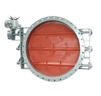
Product Image of BY42 Electric Louver Butterfly Valve

BY42 Electric Louver Butterfly ValveCharacteristic

1.Compact and lightweight design:The ultra-short face-to-face length significantly reduces the mechanical load on the pipeline compared to traditional control valves.
2.Low flow resistance and high efficiency:The streamlined blade design ensures a near-straight flow path when fully open, resulting in minimal pressure drop.
3.Low operating torque and smooth motion:The multi-axis linkage balanced structure offsets most of the fluid impact force.
4.Temperature and corrosion resistance:Available in carbon steel, stainless steel, or wear-resistant steel to adapt to high-temperature flue gas or corrosive conditions.
5.Intelligent actuation:Equipped with an intelligent actuator that supports 4-20mA signal regulation and real-time position feedback.
6.Reliable sealing performance:Optional sealing strips provide effective shut-off in both ambient and high-temperature environments.
7.Long service life:Core rotating parts utilize self-lubricating bearings to reduce mechanical wear, ensuring long maintenance cycles.
8.High degree of customization:Available in rectangular or circular structures to meet diverse installation requirements of process piping.

BY42 Electric Louver Butterfly Valvestructure principle

Structural Drawing of BY Electric Louver Butterfly Valve

List of Component Names and Materials

Part NameValve BodyLouver DiscValve StemPacking
MaterialCarbon steel, stainless steelCarbon steel, stainless steelStainless Steel, 2Cr13Flexible Graphite


BY42 Electric Louver Butterfly Valvetechnology parameter

Performance Specification Sheet

Performance Specification Sheet
Nominal Pressure0.61.0MPa
Strength test pressure0.91.5
Sealing test pressure0.661.1
Applicable Temperature-30~+250


BY42 Electric Louver Butterfly Valvestandard size

Standard requirements for external dimensions

1. The structural length of the valve shall comply with the standard of GB/T12221

2. Connecting flanges according to GB/T17241.6 standard


Outline Drawing of BY Electric Louver Butterfly Valve

Outline dimension table

DNLDD1bZ-dHH1
360180416394812-12840600
400180500450812-12922652
500220600555820-181150820
6002207006551020-181250870
7002408007551020-181340920
8002409308701024-2316321112
90026010409701224-2317201162
1000260114010701228-2318401220
1120280125011901228-2321101430
1250280138013201432-2322401495
1400300153014701436-2323701570
1500300163015701440-2324801620
1600320173016701440-2326601745
1800340193018701644-2328601845
2000360213020701648-2330601945
2200445233522921848-2332202030
2240380237023101848-2333302095
2500420263025701852-2335902225
2800440293028701860-2338902375
3000460313030701860-2340902475


Articles related to technology research and development
  • Dynamic balance electric control valve Patent

       The utility model provides a dynamically balanced electric regulating valve, which includes a valve body, a valve cover, a valve rod, a valve core installed inside the valve body and connected to the valve rod, and an actuator installed on the valve cover and connected to the top end of the valve rod. The valve body is internally provided with a water inlet chamber, a valve cavity, and a water outlet chamber in order towards the direction of medium flow. The valve core is in the shape of a bucket with its opening facing downwards. The valve core is located inside the valve cavity and is used for connecting or cutting off between the water inlet chamber and the valve cavity. The top of the valve core is provided with a through port for medium circulation. Above the through port, there is a filter cover detachably connected to the valve core. The valve rod is provided with a step, and the outside of the step is covered with an elastic sleeve that fits it. The top of the filter cover is provided with a fixing hole that fits the elastic sleeve. This utility model can filter the medium, is simple to install, time-saving, labor-saving, and can reduce the medium pressure inside the valve body, extending the service life of the valve core.

    1. A dynamic balance electric regulating valve, comprising a valve body, a valve cover, a valve rod, a valve core installed inside the valve body and connected to the valve rod, and an actuator installed on the valve cover and connected to the top end of the valve rod. Its characteristic lies in that the valve body is sequentially provided with an inlet chamber, a valve cavity, and an outlet chamber in the direction of medium flow. The valve core is in the shape of a bucket with an opening facing downwards. The valve core is located inside the valve cavity and is used for connecting or cutting off between the inlet chamber and the valve cavity. The top of the valve core is provided with a port for medium circulation. Above the port, there is a filter cover detachably connected to the valve core. The valve rod is provided with a step, and the outside of the step is covered with an elastic sleeve that fits it. The top of the filter cover is provided with a fixing hole that fits the elastic sleeve.

    2. A dynamic balance electric regulating valve according to claim 1, characterized in that the bottom of the valve body is provided with a downward-opening groove, which is connected to the valve cavity through a through hole. A bottom cover connected to the valve body is arranged below the groove, and a pressure relief mechanism is arranged inside the groove. The pressure relief mechanism comprises a force-receiving member, a pressure plate connected to the force-receiving member, and a first spring arranged below the pressure plate and abutting against the bottom cover. The force-receiving member comprises a flow diversion block protruding from the through hole and a connecting rod connected to the flow diversion block, and the connecting rod passes through the pressure plate and is locked and fixed by a nut.

    3. A dynamic balance electric regulating valve according to claim 2, characterized in that the top end of the pressure plate is pressed against the top wall of the groove, the bottom of the pressure plate is provided with a boss, and the top end of the first spring is sleeved on the boss.

    4. A dynamic balance electric control valve according to claim 1, characterized in that the valve rod is arranged through the valve cover, a sealing cover threadedly connected to the valve cover is sleeved on the valve rod, a convex ring abutting against the valve cover is arranged on the outer circumferential wall of the sealing cover, a nut cover threadedly connected to the sealing cover is arranged at the connection between the sealing cover and the valve rod, an installation groove is arranged at the connection between the nut cover and the valve rod, a plurality of O-rings adapted to the valve rod are stacked in the installation groove, and a packing gland threadedly connected to the installation groove is arranged above the O-rings.

    5. A dynamic balance electric control valve according to claim 4, characterized in that a second spring is arranged between the packing gland and the O-ring.

    6. A dynamic balance electric control valve according to claim 5, characterized in that a sealing ring adapted to the valve rod is arranged inside the nut cover below the installation groove.

    7. A dynamic balance electric control valve according to claim 6, characterized in that the bottom of the sealing cover is provided with a thrust ring that is threadedly connected to the sealing cover and abuts against the bottom end of the valve cover.

    8. A dynamic balance electric regulating valve according to claim 1, characterized in that the top surface of the elastic sleeve is higher than the top surface of the filter cover.

    9. A dynamic balance electric control valve according to claim 8, characterized in that the filter cover is connected to the valve core through threads.