Your location:

/ Valve products / control valve / Electric Control Valve / ZDG High-Performance Shut-off Butterfly Valve
全国销售热线:0577-67378222

Product classification of Kaiweixi

KAI WEI XI CHAN PIN FEN LEI
  • ZDG High-Performance Shut-off Butterfly Valve

  • More Electric Control Valve>>

  • More control valve>>

  • More valve>>

Contact Us
  • Phone:+86(577)6730 7899
  • Mobile:+86 195 1816 9569
  • Fax:+86(577)6738 7099
  • Email:Lucas@kaiweixi.com
  • Address:No. 1, Linxia Road, Oubei Street, Yongjia County, Wenzhou City, Zhejiang Province,china
  • Website:https://www.kaiweixi.com
Other valve products you may need
  • D971X Electric Rubber-Lined Butterfly Valve
  • VQ Electric V-port Ball Control Valve
  • ZDLP Series Electronic Electric Single-Seated Control Valve
  • CV3000 Electric Cage-Guided Control Valve
  • 700X Pump Control Valve
ZDG High-Performance Shut-off Butterfly Valve

ZDG High-Performance Shut-off Butterfly Valve

  • Model:ZDG43H-16C/ZDG43H-25C/ZDG43H-40C/ZDG43H-64C/ZDG43Y-16P/ZDG43Y-25P/ZDG43Y-40P/ZDG43Y-64P
  • Specification:DN50~500
  • Temperature:-29~350℃
  • Medium:Large-diameter rapid shut-off applications requiring tight sealing
  • Pressure:PN1.6~6.4MPa
  • Connection method:Flange
  • Driving method:Electric
  • Material:Carbon steel, stainless steel
x

Add QR code to serve you!

x

Add QR code to serve you!

x

Add QR code to serve you!

x
ZDG High-Performance Shut-off Butterfly ValveOverview

The ZDG high-performance shut-off butterfly valve is a high-end pipeline control unit integrating a high-thrust electric actuator with a precision eccentric butterfly valve body. Specifically engineered for large-diameter, high-differential pressure conditions in industrial systems that require strict isolation, the valve utilizes high torque from the actuator to rotate the disc 0-90 degrees for instantaneous shut-off or opening. Utilizing advanced double or triple offset structures, this series offers low operating torque, minimal sealing surface wear, and high sealing reliability, serving as a superior alternative to bulky traditional gate or ball valves. The ZDG series maintains excellent shut-off performance in high-temperature and high-pressure environments and is widely used in safety control loops for petroleum, chemical, power, and district heating industries due to its erosion-resistant design.

Product Image of ZDG High-Performance Shut-off Butterfly Valve

ZDG High-Performance Shut-off Butterfly ValveCharacteristic

1.Eccentric geometry for frictionless operation:Utilizes double or triple offset logic so the disc detaches from the seat immediately upon opening, fundamentally eliminating friction. This significantly reduces torque and extends seal life.
2.Superior bi-directional sealing and shut-off:Precision-ground sealing pairs offer multi-layered metal hard-seal or resilient soft-seal options. It achieves bubble-tight closure meeting ANSI Class VI standards, ensuring system safety.
3.Powerful and sensitive electric drive:Equipped with high-performance intelligent actuators featuring large torque and rapid response. Supports remote automation and local manual override with integrated overload and phase protection.
4.Low flow resistance and energy efficiency:The disc's streamlined design provides a near-straight flow path when fully open. This minimal resistance reduces pipeline pressure drop and pumping energy consumption.
5.Compact and lightweight layout:Compared to same-sized gate valves, the face-to-face length is shorter and weight is lower. This saves space and reduces mechanical loads and support costs for the piping system.
6.Durable material configurations:Body and disc are available in carbon steel, stainless steel, or special alloys. Sealing surfaces can be hard-faced with alloys for exceptional resistance to erosion and wear in harsh media.
7.Inherent fire-safe and anti-static design:Complies with API 607 fire safety standards. It maintains basic sealing integrity during extreme fire events and features reliable anti-static grounding for hazardous chemical sites.
8.Low O&M cost modularity:Actuator-to-body connections follow ISO standards. Wearing parts like seal rings are replaceable without removing the valve body, shortening maintenance downtime.

ZDG High-Performance Shut-off Butterfly Valvestructure principle

Structural Drawing of ZDG High-Performance Shut-off Butterfly Valve


List of Component Names and Materials

Part NameCommon Materials
Valve BodyCarbon steel, stainless steel
DiscGrey Cast Iron, Ductile Cast Steel, Cast Steel, Stainless Steel
Stem2Cr13, Stainless Steel
Seal RingVarious Rubbers, PTFE, Stainless Steel
PackingO-ring, Flexible Graphite


ZDG High-Performance Shut-off Butterfly Valvetechnology parameter

Performance Specification Sheet

Performance Specification Sheet
Nominal Pressure1.62.54.06.4MPa
Strength test pressure2.43.86.09.6
Sealing test pressure1.762.84.47.04
Applicable Temperature-29~350


ZDG High-Performance Shut-off Butterfly Valvestandard size

Standard requirements for external dimensions

1.Design & Manufacturing: GB12237-89, API608, API 6D, JPI 7S-48, BS5351, DIN3357

2.Flange Dimensions: JB/T74~90, GB9112~9131, HGJ44~76, SH3406, ANSI B16.5, JIS B2212~2214, NF E29-211, DIN2543

3.Face-to-Face Dimensions: GB12221-89, ANSI B16.10, JIS B2002, NF E29-305, DIN3202

4.Inspection & Testing: JB/T 9092, API 598
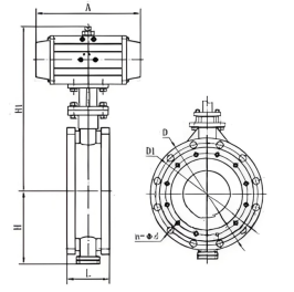

Outline Drawing of ZDG High-Performance Shut-off Butterfly Valve

Outline dimension table(Unit:mm)

SizeAHH1ΦD (PN10)ΦD (PN16)ΦD1n-Φd (PN10)n-Φd (PN16)L
DN5016813170125125974-204-2042
DN65219148721451451124-204-2045
DN80249155901601601274-204-2045
DN1002741711081801801604-204-2052
DN1252741931202102101884-204-2055
DN1503552101342402402164-234-2356
DN2004172461662952952684-234-2361
DN2504522822063503553304-234-2666
DN3005853112344004103844-234-2677
DN3506853452654604704224-234-2677
DN4007433772975155254734-264-3086
DN4508574123315655855264-264-30104
DN5009354403616206505774-264-33130


Articles related to technology research and development
  • Dynamic balance electric control valve Patent

       The utility model provides a dynamically balanced electric regulating valve, which includes a valve body, a valve cover, a valve rod, a valve core installed inside the valve body and connected to the valve rod, and an actuator installed on the valve cover and connected to the top end of the valve rod. The valve body is internally provided with a water inlet chamber, a valve cavity, and a water outlet chamber in order towards the direction of medium flow. The valve core is in the shape of a bucket with its opening facing downwards. The valve core is located inside the valve cavity and is used for connecting or cutting off between the water inlet chamber and the valve cavity. The top of the valve core is provided with a through port for medium circulation. Above the through port, there is a filter cover detachably connected to the valve core. The valve rod is provided with a step, and the outside of the step is covered with an elastic sleeve that fits it. The top of the filter cover is provided with a fixing hole that fits the elastic sleeve. This utility model can filter the medium, is simple to install, time-saving, labor-saving, and can reduce the medium pressure inside the valve body, extending the service life of the valve core.

    1. A dynamic balance electric regulating valve, comprising a valve body, a valve cover, a valve rod, a valve core installed inside the valve body and connected to the valve rod, and an actuator installed on the valve cover and connected to the top end of the valve rod. Its characteristic lies in that the valve body is sequentially provided with an inlet chamber, a valve cavity, and an outlet chamber in the direction of medium flow. The valve core is in the shape of a bucket with an opening facing downwards. The valve core is located inside the valve cavity and is used for connecting or cutting off between the inlet chamber and the valve cavity. The top of the valve core is provided with a port for medium circulation. Above the port, there is a filter cover detachably connected to the valve core. The valve rod is provided with a step, and the outside of the step is covered with an elastic sleeve that fits it. The top of the filter cover is provided with a fixing hole that fits the elastic sleeve.

    2. A dynamic balance electric regulating valve according to claim 1, characterized in that the bottom of the valve body is provided with a downward-opening groove, which is connected to the valve cavity through a through hole. A bottom cover connected to the valve body is arranged below the groove, and a pressure relief mechanism is arranged inside the groove. The pressure relief mechanism comprises a force-receiving member, a pressure plate connected to the force-receiving member, and a first spring arranged below the pressure plate and abutting against the bottom cover. The force-receiving member comprises a flow diversion block protruding from the through hole and a connecting rod connected to the flow diversion block, and the connecting rod passes through the pressure plate and is locked and fixed by a nut.

    3. A dynamic balance electric regulating valve according to claim 2, characterized in that the top end of the pressure plate is pressed against the top wall of the groove, the bottom of the pressure plate is provided with a boss, and the top end of the first spring is sleeved on the boss.

    4. A dynamic balance electric control valve according to claim 1, characterized in that the valve rod is arranged through the valve cover, a sealing cover threadedly connected to the valve cover is sleeved on the valve rod, a convex ring abutting against the valve cover is arranged on the outer circumferential wall of the sealing cover, a nut cover threadedly connected to the sealing cover is arranged at the connection between the sealing cover and the valve rod, an installation groove is arranged at the connection between the nut cover and the valve rod, a plurality of O-rings adapted to the valve rod are stacked in the installation groove, and a packing gland threadedly connected to the installation groove is arranged above the O-rings.

    5. A dynamic balance electric control valve according to claim 4, characterized in that a second spring is arranged between the packing gland and the O-ring.

    6. A dynamic balance electric control valve according to claim 5, characterized in that a sealing ring adapted to the valve rod is arranged inside the nut cover below the installation groove.

    7. A dynamic balance electric control valve according to claim 6, characterized in that the bottom of the sealing cover is provided with a thrust ring that is threadedly connected to the sealing cover and abuts against the bottom end of the valve cover.

    8. A dynamic balance electric regulating valve according to claim 1, characterized in that the top surface of the elastic sleeve is higher than the top surface of the filter cover.

    9. A dynamic balance electric control valve according to claim 8, characterized in that the filter cover is connected to the valve core through threads.