Your location:

/ Valve products / check valve / Swing check valve / H76W Dual Plate Check Valves
全国销售热线:0577-67378222

Product classification of Kaiweixi

KAI WEI XI CHAN PIN FEN LEI
  • H76W Dual Plate Check Valves

  • More Swing check valve>>

  • More check valve>>

  • More valve>>

Contact Us
  • Phone:+86(577)6730 7899
  • Mobile:+86 189 6779 6135
  • Fax:+86(577)6738 7099
  • Email:Yannie@kaiweixi.com
  • Address:No. 1, Linxia Road, Sanqiao Industrial Zone, Oubei Street, Yongjia County, Zhejiang Province,china
  • Website:https://www.kaiweixi.com
Other valve products you may need
  • HC44X Swing Flex Check Valve
  • H76X Wafer Dual Disc Check Valve
  • HH49X Micro Resistance Slow Closing Butterfly Check Valve
  • H44W Swing Check Valve
  • H44W API Swing Check Valve
H76W Dual Plate Check Valves

H76W Dual Plate Check Valves

  • Model:H76W-10C/H76W-25C/H76W-40C/H76W-64P/H76W-100P/H76W-160P
  • Specification:DN50-DN1200
  • Temperature:≤ 425 ℃
  • Medium:Water, Steam, Oil Products
  • Pressure:PN10-PN160
  • Connection method:wafer
  • Driving method:automated
  • Material:WCB、Stainless Steel
x

Add QR code to serve you!

x

Add QR code to serve you!

x

Add QR code to serve you!

x
H76W Dual Plate Check ValvesOverview

Overview

The H76W dual-plate check valve is an energy-efficient check valve that features a twin-disc design and operates automatically based on medium flow. It typically uses a wafer-type connection. The valve body is commonly made of stainless steel, cast steel, or ductile iron, with its two discs performing a symmetrical rotary motion around the same shaft. The valve can be installed either horizontally or vertically. When the medium flows in the forward direction, it pushes the dual discs to open smoothly, and the flow path is nearly straight-through, resulting in low pressure loss. When the medium stops or flows in reverse, the dual discs close rapidly under the combined effect of spring force and reverse medium pressure, ensuring reliable sealing and fast shut-off. This valve is specifically designed for pipeline systems with limited installation space and the need for quick closure. It is widely used in water supply and drainage, fire protection systems, HVAC, and industrial circulating water projects, serving as a compact, economical, and practical pipeline protection device.

H76W Dual Plate Check Valves Product Image

H76W Dual Plate Check ValvesCharacteristic

Features

1.Quick opening and closing due to dual-disc design: The two symmetrical discs rotate around the same shaft, resulting in a short disc stroke and fast closing speed, which effectively reduces water hammer impact. It is especially suitable for pipeline systems with requirements on closing time.

2.Compact structure with wafer connection: The wafer-type connection makes the valve body length only about one-third that of a flanged check valve. It is lightweight, occupies little space, and is easy to install in narrow pipeline locations.

3.Low flow resistance and significant energy saving: The discs open at a large angle, and the flow path is nearly straight-through when fully open, resulting in low fluid resistance and low pressure loss. Long-term operation can effectively reduce pumping energy consumption.

4.Flexible installation and strong adaptability: It can be installed horizontally or vertically (with medium flow from bottom to top). The spring-assisted closing ensures reliable sealing at various installation angles, offering a wide range of applications.

5.Simple maintenance, economical and practical: The structure is simple with a low number of parts, resulting in a low failure rate. The wafer design allows for easy disassembly, facilitating online inspection and maintenance. With high cost-effectiveness, it is widely used in water supply and drainage, fire protection, HVAC, and industrial circulating water systems.

H76W Dual Plate Check Valvesstructure principle

H76W Dual Plate Check Valves Structure Diagram

Parts Name Material List

阀体body阀瓣disc阀座seat阀瓣座disc seta弹簧spring介质接触件Wetted parts
A216WCB/A105A351 CF8410SS/StelliteSame as discInconelX-750410SS
A216 WCB/A105A351 CF8VITON/BUNA/EPDMSame as discInconelX-750410SS
A216WCB/A105A351 CF8M316SS/StelliteSame as discInconelX-750316SS
A216WCB/A105A351 CF8MVITON/BUNA/EPDMSame as discInconelX-750316SS
A352LCC/A350 LF2A351 CF8M316SS/StelliteSame as discInconelX-750316SS
A352LCC/A350 LF2A351 CF8MVITON/BUNA/EPDMSame as discInconelX-750316SS
A351 CF8M/A182F316A351 CF8MSame as bodySame as discInconelX-750316SS
A351 CF8M/A182F316A351 CF8MVITON/BUNA/EPDMSame as discInconelX-750316SS
A890 GR4A/A182F51A890 GR 4ASame as bodySame as discInconelX-750A182F51
A890 GR 5A/A182F53A890 GR 5ASame as bodySame as discInconelX-750A182F53
UNS S31254UNS S31254Same as bodySame as discInconelX-750254-SMO
UNS N26625UNSN26625Same as bodySame as discInconelX-750Inconel 625


H76W Dual Plate Check Valvestechnology parameter
性能规范表Performance Specification
公称压力Nominal Pressure1.0-16МPA
强度试验压力Shell Test1.5-24
密封试验压力Seal Test1.1-17.6
适用温度Suitable Temp.≤425


H76W Dual Plate Check Valvesstandard size

Dimensions Standard Requirements

1. The structural length of the valve shall conform to the standard ASME16.10.

2. The connecting flange shall conform to the standard ASME16.50.  

H76W Dual Plate Check Valves View Drawing

H76W Dual Plate Check Valves Dimensions Table

Pressure RatingNominal Size DNDimensionsPipe FlangeWeight (kg)
LDD1D2Diam.of Bolts CircleNo of Bolt holesDiam.of Bolt holesDiam.of BoltsLength of Bolts
PN1050601085155125418M161502.2
65671286568145818M161553.1
80731428082160818M161604.3
10073162102108180818M161656.3
12586192127130210B18M161808.4
15098218152165240822M2020512.6
200127273203220295822M2023524
2501463282542703501222M2025540
3001813783053204001222M2029066
3501844383373504601622M2029583
4001914893874005151626M24310102
4502035394384385652026M24325124
5002195944954956202026M24345150
6002226965955957252030M27355203
7003058116856858402430M27440380
8003059187807809502433M30450580
900368101887587510502833M30520665
1000432112497597511602836M33590880
120052413401165116513803239M366951470

Pressure RatingNominal Size DNDimensionsPipe FlangeWeight (kg)
LDD1D2Diam.of Bolts CircleNo of Bolt holesDiam.of Bolt holesDiam of BoltsLength of Bolts
PN1650601085155125418M161502.2
65671286568145818M161553.1
80731428082160818M161604.3
10073162102108180818M161656.3
12586192127130210818M161808.4
15098218152165240822M2020512.6
2001272732032202951222M2023524
2501463292542703551226M2426540
3001813843053204101226M2430566
3501844443373504701626M2431083
4001914963874005251630M27330102
4502035564384385852030M27345124
5002196184954956502033M30370150
6002227325955957702036M33380203
7003058026856858402436M33470380
8003059127807809502439M36475580
900368101287587510502839M36545665
1000432112697597511702842M39620880
120052413401165116513903248M457351470

Pressure RatingNominal Size DNDimensionsPipe FlangeWeight (kg)
LDD1D2Diam.of Bolts CircleNo.of Bolt holesDiam.of Bolt holesDiam.of BoltsLength of Bolts
PN2550601085155125418M161502.2
65671286568145818M161603.1
80731428082160818M161704.3
10073168102108190822M201806.3
12586194127130220826M242058.4
15098224152165250826M2422013.5
2001272842032203101226M2425526
2501463412542703701230M2728543
3001814013053204301630M2732570
3501844583373504901633M3034090
4001915153874005501636M33360110
4502035654384386002036M33375135
5002196224954956602036M33395158
6002227325955957702039M36410220
7003058316856858752442M39500400
8003059427807809902448M45520600
900368104087587510902848M45590685
1000432115597597512102856M52675900
120052413651165116514203256M527901510

Pressure RatingNominal Size DNDimensionsPipe FlangeWeight kg)
LDD1D2Diam.of Bolts CircleNo.of Bolt holesDiam.of Bolt holesDiam.of BoltsLength of Bolts
PN4050601085155125418M161502.5
65671286568145818M161604
80731428082160818M161705
10073168102108190822M201807
12586194127130220826M2420511.2
15098224152165250826M2422016.5
2001272912032203201230M2727031.5
2501463532542703851233M3030049.5
3001814183053204501633M3034581
3502224753373435101636M33400117
4002325473874005851639M36425158
4502645724384386102039M36470200
5002926264954956702042M39505285
6003187455955957952048M45575380

Pressure RatingNominal Size DNDimensionsPipe FlangeWeight (kg)
LDD1D2Diam.of Bolts CircleNo of Bolt holesDiam.of Bolt holesDiam of BoltsLength of Bolts
RFRTJ
PN6350601145155135422M201701852.5
65671386568160822M201801954
80731488082170822M201902055
10079174102108200826M242102259
125105211127130240830M2725026514.5
150136248152165280833M3029030527
2001653102002103451236M3333535048
2502133622502554001236M3339541093.5
3002294223003004601636M33420435114.5
3502734873353355251639M36480495187
4003055413853855851642M39525540261

Pressure RatingNominal Size DNDimensionsPipe FlangeWeight (kg)
LDD1D2Diam.of Bolts CircleNo of Bot holesDiam.of Bolt holesDiam.of BoltsLength of Bolts
RFRTJ
PN10050601205155145426M241852002.5
65671446568170826M241952104
80731548082180826M242052205
10079181102108210830M272252409
125105218127130250833M3026528014.5
1501362581521652901233M3030532027
2001653242002103601236M3335537048
2502133922502554301239M3642544093.5
3002294563003005001642M39465480114.5
3502735103353355601648M45535550187
4003055703853856201648M45585600261

Pressure RatingNominal Size DNDimensionsPipe FlangeWeight (kg)
LDD1D2Diam.of Bolts CircleNo of Bot holesDiam.of Bolt holesDiam.of BoltsLength of Bolts
RFRTJ
PN16050701205055145426M242102256
65831446568170826M242352507.5
80831547582180826M242452609.6
100102181100108210830M2728029517
125110218125130250833M3030532028
1501592581501602901233M3036538541
2002063252002103601236M3342544580
2502413892502554301242M39495515135
3002924593003005001642M39570600212


Articles related to technology research and development
  • Slow-closing wafer check valve patent

       The utility model provides a slow-closing wafer check valve, which includes a valve body, a valve disc, a valve shaft, and a torsion spring sleeved on the valve shaft. The valve body is provided with a medium channel for medium circulation in the axial direction, which includes an inlet end and an outlet end. The valve disc, valve shaft, and torsion spring are symmetrically arranged in two groups relative to the center of the valve body. The utility model further includes a damping device located at the inlet end, which includes a cylinder inserted on the valve body, a piston rod located inside the cylinder, a spring, and a cover connected to the outer end of the cylinder. The cylinder is provided with a first cavity and a second cavity that are connected and communicated. The cross-section of the second cavity is square, and its cross-sectional area is larger than that of the first cavity. One end of the piston rod located inside the medium channel is provided with a movable block. The utility model has low noise and technical characteristics of quick opening, slow closing, and water hammer elimination, enabling light-load pump start-up and preventing the generation of water hammer during pump shutdown.
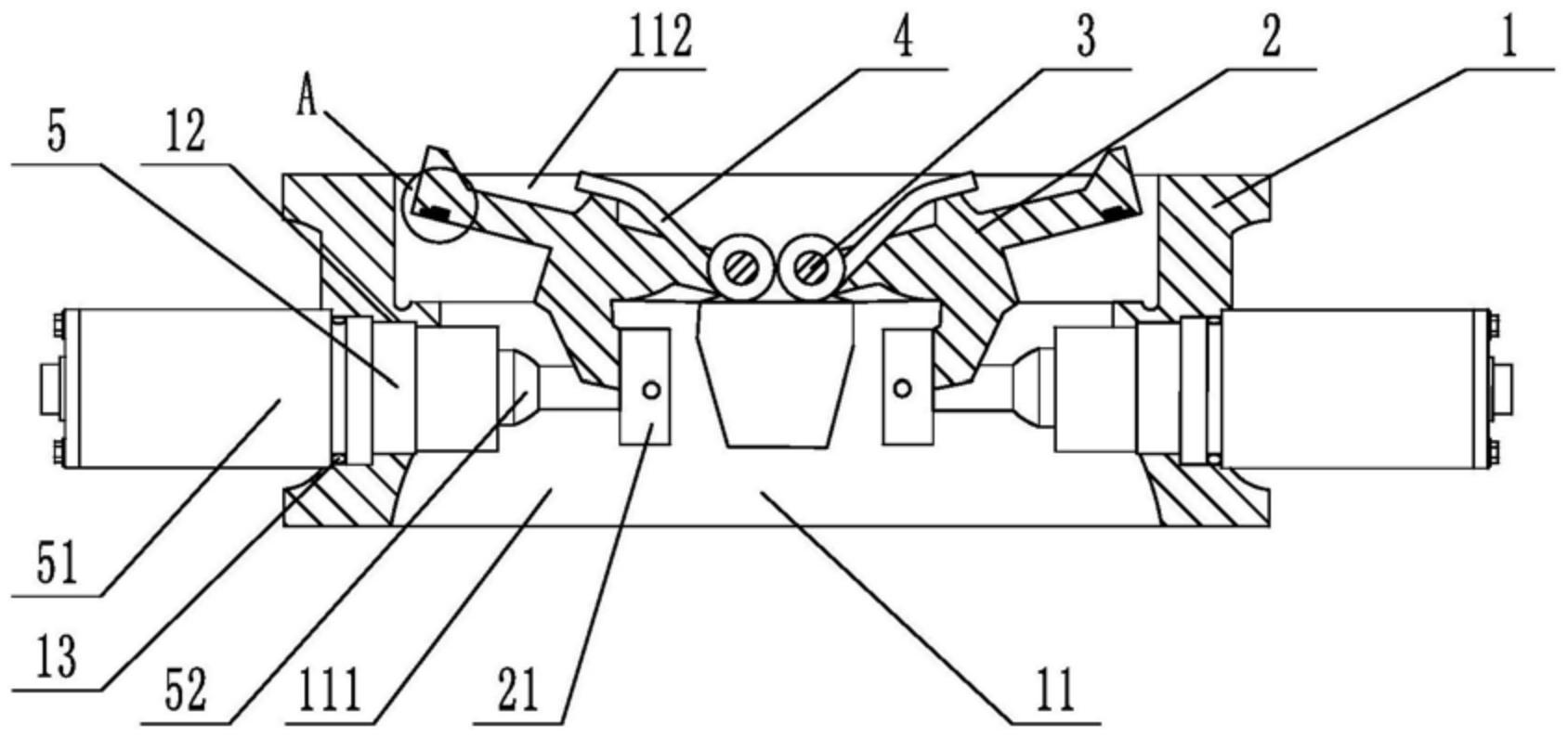
    1. A slow-closing wafer check valve, comprising a valve body, a valve disc, a valve shaft, and a torsion spring sleeved on the valve shaft. The valve body is provided with a medium passage for medium circulation in the axial direction, and the medium passage includes an inlet end and an outlet end. The valve disc, valve shaft, and torsion spring are symmetrically arranged in two groups relative to the center of the valve body. The valve also comprises a damping device located at the inlet end. The damping device includes a cylinder inserted on the valve body, a piston rod located inside the cylinder, a spring, and a cover connected to the outer end of the cylinder. The cylinder is provided with a first cavity and a second cavity that are connected and communicated. The cross-section of the second cavity is square, and the cross-sectional area of the second cavity is larger than that of the first cavity. One end of the piston rod is located inside the second cavity, and the other end penetrates through the first cavity and is located inside the medium passage. The end of the piston rod located inside the medium passage is provided with a movable block, and the end of the piston rod located inside the second cavity is provided with an external thread. The second cavity is provided with a limit plate that is adapted to and threadedly connected with the piston rod. The spring is sleeved on the piston rod, with one end abutting against the limit plate and the other end abutting against the inner wall of the second cavity. The side of the valve disc facing the piston rod is provided with a driving block that cooperates with the movable block. During the closing process of the valve disc, the side of the driving block facing the center of the valve body cooperates with the movable block to achieve displacement of the piston rod relative to the cylinder towards the center of the valve body. The damping device is symmetrically arranged in two groups relative to the center of the valve body.

    2. A slow-closing wafer check valve according to claim 1, characterized in that a square hole is axially provided at the end of the piston rod located in the second cavity, an adjuster is inserted at a position on the cover corresponding to the square hole, a driving rod adapted to the square hole is provided at the end of the adjuster, and the adjuster is rotatable relative to the cover.

    3. A slow-closing wafer check valve according to claim 2, characterized in that a limit slot is provided at the connection between the cover and the regulator, and a limit mechanism is arranged inside the limit slot. The limit mechanism comprises a ball, a tower spring connected to the ball, and a positioning column for fixing the tower spring. At least four engaging slots adapted to the ball are provided circumferentially at the connection between the regulator and the cover.

    4. A slow-closing wafer check valve according to claim 3, characterized in that the top edge of the engaging groove is provided with a rounded corner.

    5. A slow-closing wafer check valve according to claim 1, characterized in that the valve body is provided with a stepped groove adapted to the cylinder body.

    6. A slow-closing wafer check valve according to claim 5, characterized in that a sealing ring is sleeved at the connection between the cylinder and the valve body.

    7. A slow-closing wafer check valve according to claim 1, characterized in that the valve disc is provided with a build-up welding layer that is sealed with the valve body. 8. A slow-closing wafer check valve according to claim 7, characterized in that one side of the build-up welding layer is provided with vulcanized rubber that is sealed with the valve body.