Your location:

/ Valve products / Gate valve / Knife Gate Valve / PZ643TC Pneumatic Ceramic Wear-Resistant Knife Gate Valve
全国销售热线:0577-67378222

Product classification of Kaiweixi

KAI WEI XI CHAN PIN FEN LEI
  • PZ643TC Pneumatic Ceramic Wear-Resistant Knife Gate Valve

  • More Knife Gate Valve>>

  • More Gate valve>>

  • More valve>>

Contact Us
  • Phone:+86(577)6730 7899
  • Mobile:+86 1815 7711 652
  • Fax:+86(577)67387099
  • Email:merry@kaiweixi.com
  • Address:No. 1, Linxia Road, Oubei Street, Yongjia County, Wenzhou City, Zhejiang Province,china
  • Website:https://www.kaiweixi.com
Other valve products you may need
  • PZ643W Pneumatic Wafer Type Knife Gate Valve
  • PZL73H Sprocket Operated Lug Type Knife Gate Valve
  • PZ573H Bevel Gear Operated Knife Gate Valve
  • PZ73X Slab Type Knife Gate Valve
  PZ643TC Pneumatic Ceramic Wear-Resistant Knife Gate Valve

PZ643TC Pneumatic Ceramic Wear-Resistant Knife Gate Valve

  • Model:PZ643TC-6C/PZ643TC-10C/PZ643TC-16C/PZ643TC-6P/PZ643TC-10P//PZ643TC-16P
  • Specification:DN50-DN600
  • Temperature:<=150℃
  • Medium:Pulp slurry, etc.
  • Pressure:PN6-PN16
  • Connection method:Flanged, Butt-welded
  • Driving method:Pneumatic
  • Material:Cast steel, stainless steel + ceramic
x

Add QR code to serve you!

x

Add QR code to serve you!

x

Add QR code to serve you!

x
PZ643TC Pneumatic Ceramic Wear-Resistant Knife Gate ValveOverview

Overview                        

The PZ643TC Pneumatic Ceramic Wear-Resistant Knife Gate Valve is a high-performance automated valve specifically engineered for extreme abrasive service conditions. Driven by a pneumatic actuator, it interrupts or permits media flow by vertically lifting or lowering a knife gate with sharp edges. Its core innovation lies in the use of high-tech structural ceramics (such as alumina or silicon carbide) for critical flow-path components (gate, seat, and valve body lining), with “TC” denoting “Ceramic.” The wafer-type connection ensures an exceptionally compact structure, optimized for handling highly abrasive slurries and powdered media. This product represents the ultimate solution for handling highly abrasive and corrosive media. It finds primary application in extremely demanding processes such as ash removal systems in thermal power plants, pulverized coal and water-coal slurry conveyance in the coal industry, tailings and concentrate pipelines in mining operations, dust collection systems in steel mills, and the handling of high-hardness catalysts and granular materials in chemical plants. It serves as the core equipment ensuring long-term, stable, and low-maintenance operation in such high-wear systems.

Product drawing of PZ643TC pneumatic ceramic wear-resistant knife gate valve


PZ643TC Pneumatic Ceramic Wear-Resistant Knife Gate ValveCharacteristic

Features:

1. Ultra-wear-resistant ceramic internals: All critical components in contact with the medium are crafted from ultra-high-hardness, highly wear-resistant engineering ceramics. Their wear resistance exceeds that of traditional metals by tens to hundreds of times, revolutionizing valve service life.

2. Pneumatic Rapid Automation: Equipped with a high-performance pneumatic actuator, it delivers swift opening/closing actions and stable torque output. Seamlessly integrates with automated control systems for precise, rapid remote control and high-frequency shut-off.

3. Blade-edge design for clog and jam prevention: The ceramic gate plate features sharp edges that effortlessly cut through high-concentration, high-hardness slurries and fibers. Its ultra-smooth ceramic surface significantly reduces material adhesion and blockage risks.

4. Exceptional Corrosion Resistance: Ceramic materials exhibit extreme chemical stability, offering outstanding resistance to most corrosive media including acids, alkalis, and salts. Ideal for harsh environments involving both abrasion and corrosion.

5. Compact Wafer-Type Structure: Utilizing wafer-type connections, this design features a short structural length, relatively light weight, and minimal installation space requirements. It facilitates seamless integration within complex piping systems.

PZ643TC Pneumatic Ceramic Wear-Resistant Knife Gate Valvestructure principle

PZ643TC Pneumatic Ceramic Wear-Resistant Knife Gate Valve Structural Diagram

Part Name Material

序号/Serial Number名称/Body材料/Materials
1阀体/Valve bodyWCB + 陶瓷/WCB+Ceramics
2阀板/Valve plate304 + 陶瓷/304 + Ceramic
3填料/FillerPTFE/聚四氟乙烯
4压盖/CappingWCB/碳素钢铸件
5螺栓/bolt35号碳素结构钢/35#
6支架/Bracket45#+Cr/45 号碳素结构钢
7螺母/NutA105/A105 碳素钢锻件牌
8活塞杆/Piston rod45#+Cr/45 号碳素结构钢
9气缸/Cylinder铝合金/aluminum alloy
10定位器/LocatorWCB/碳钢
11阀体内衬\Valve body lining氧化铝陶瓷\Alumina Ceramics


PZ643TC Pneumatic Ceramic Wear-Resistant Knife Gate Valvetechnology parameter


Performance Specification Table

性能项目/Performance Item参数值/ Parameter Value
公称压力/Nominal Pressure1.0MPa
强度试验/Strength Test1.5MPa
密封实验/Sealing Test/
适用温度/Operating Temperature≤250℃


Dimension Standard Requirements

1. Structural length of valves shall comply with GB 13927.

2. Connecting flanges shall comply with GB/T 17241.6.


PZ643TC Pneumatic Ceramic Wear-Resistant Knife Gate Valvestandard size

PZ643TC Pneumatic Ceramic Wear-Resistant Knife Gate Valve Outline Drawing

Dimension Chart

DNLDD1n-dH□a×a
50481651254-1854780×80
6548180145607
8050195160632100×100
100502181808-18742115×115
12557255210820145×145
15057280240900
200703422958-231130220×220
2507040235012-231252
300764804001480270×270
3507653046016-231643
4008959451516-251776
4508963556520-251970
5001146806202157340×340
60011480572520-302476


Articles related to technology research and development
  • soft-sealed gate valve patented

       The utility model discloses a novel soft-seal gate valve, which includes a valve body, a valve cover, a valve rod, a valve chamber, and a rubber-coated gate plate. The valve rod penetrates through the valve cover and is connected to the rubber-coated gate plate. The valve chamber includes a medium channel for medium circulation and a connecting chamber that is connected to the medium channel and corresponds to the valve cover. The rubber-coated gate plate is adapted to the connecting chamber and used to cut off or connect the medium channel. The medium channel includes an inlet end and an outlet end. Guide rails are arranged on the inner wall of the connecting chamber on both sides opposite to the rubber-coated gate plate. Both sides of the rubber-coated gate plate are provided with metal sliders, and the metal sliders are provided with sliding grooves that are adapted to the guide rails. Compared to existing soft-seal gate valves, the utility model has good sealing performance, convenient disassembly and assembly, and a long service life for the rubber-coated gate plate.
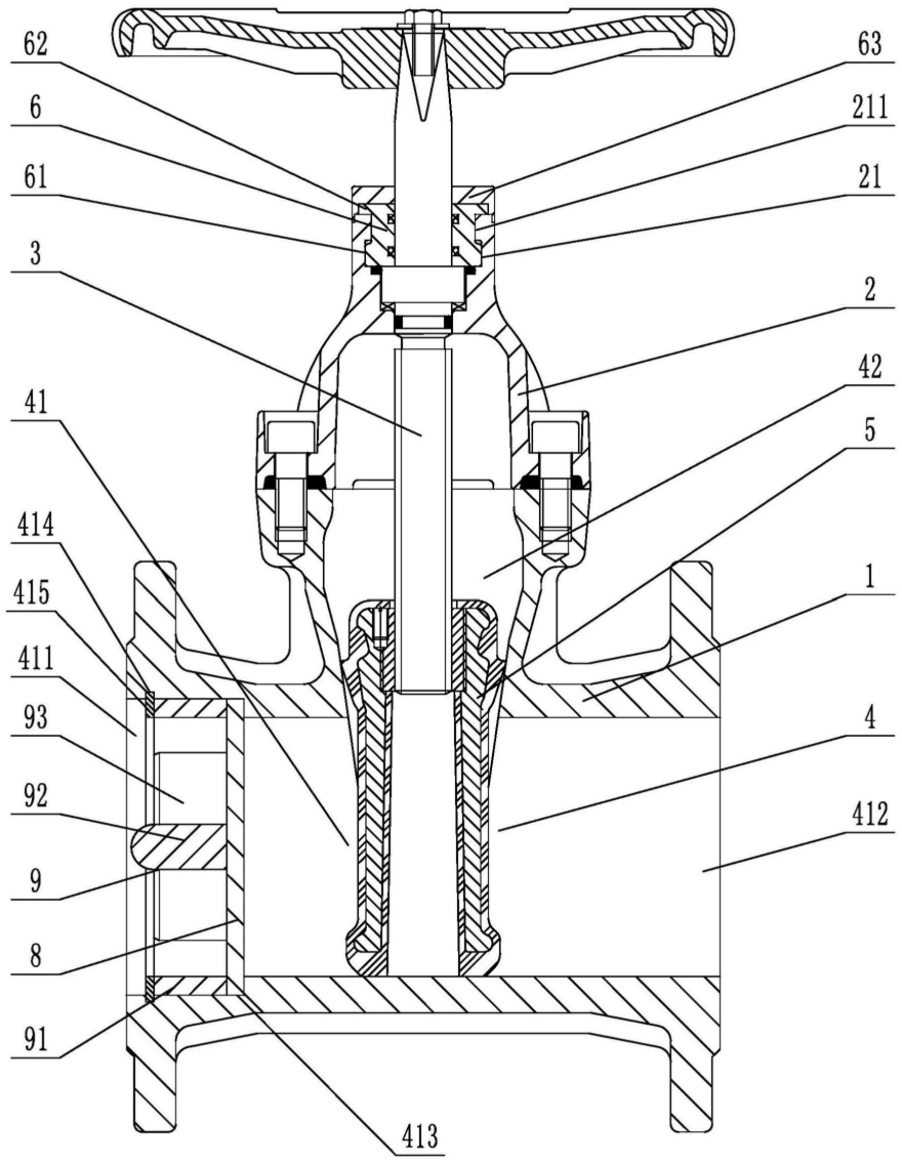
    1. A novel soft-seal gate valve comprises a valve body, a valve cover, a valve rod, a valve chamber, and a rubber-coated gate plate. The valve rod penetrates through the valve cover and is connected to the rubber-coated gate plate. The valve chamber includes a medium passage for medium circulation and a connecting chamber connected to the medium passage and corresponding to the valve cover. The rubber-coated gate plate is fitted to the connecting chamber and used to cut off or connect the medium passage. The medium passage includes an inlet end and an outlet end. The utility model is characterized in that guide rails are arranged on both sides of the rubber-coated gate plate on the inner wall of the connecting chamber, metal sliding blocks are arranged on both side walls of the rubber-coated gate plate, sliding grooves adapted to the guide rails are opened on the metal sliding blocks, a sealing groove is opened on the top of the valve cover in the axial direction relative to the valve rod, a clamping block is arranged at the opening of the sealing groove, at least three clamping blocks are arranged circumferentially at intervals relative to the central axis of the sealing groove, a sealing seat fitted to and sleeved on the valve rod is arranged inside the sealing groove, a fixed block corresponding to the rotational fit of the clamping block is arranged on the outer circumferential wall at the bottom of the sealing seat, a pressing block abutting against the top surface of the valve cover is arranged on the top of the sealing seat, and a rubber sleeve is sleeved on the top of the valve cover.

    2. A novel soft-seal gate valve according to claim 1, characterized in that a limit opening is provided at the position on the pressure block corresponding to the gap between two adjacent clamping blocks, a limit groove is provided on the end face of the pressure block, a thrust stopper is provided on the sealing seat, and the thrust stopper comprises a fixed disc adapted to the limit groove and a thrust block provided on the outer circumferential wall of the fixed disc and adapted to the limit opening.

    3. A novel soft seal gate valve according to claim 2, characterized in that a limiting block is arranged on the outer circumferential wall of the sealing seat at a position between two adjacent fixing blocks, and a clamping groove adapted to the limiting block is provided on the thrust block.

    4. A novel soft seal gate valve according to claim 1, characterized in that a stepped groove is provided in the valve body at the inlet end, and a filter screen is arranged inside the stepped groove.

    5. A novel soft-seal gate valve according to claim 4, characterized in that the side of the filter screen facing the inlet end is provided with a flow dividing device, which comprises a fixing ring that fits with interference with the inner wall of the stepped groove, a connecting column located on the central axis of the fixing ring, and a flow dividing plate connected to the fixing ring and the connecting column. The side of the stepped groove located on the inlet end facing the fixing ring is provided with an inner groove, and an elastic snap ring is arranged in the inner groove.

    6. A novel soft seal gate valve according to claim 5, characterized in that the side wall of the diverter plate facing the inlet end has a triangular cross-section.

    7. A novel soft seal gate valve according to claim 5, characterized in that one end of the connecting column facing the inlet end is hemispherical