Your location:

/ Valve products / Gate valve / Knife Gate Valve / PZ643W Pneumatic Wafer Type Knife Gate Valve
全国销售热线:0577-67378222

Product classification of Kaiweixi

KAI WEI XI CHAN PIN FEN LEI
  • PZ643W Pneumatic Wafer Type Knife Gate Valve

  • More Knife Gate Valve>>

  • More Gate valve>>

  • More valve>>

Contact Us
  • Phone:+86(577)6730 7899
  • Mobile:+86 1815 7711 652
  • Fax:+86(577)67387099
  • Email:merry@kaiweixi.com
  • Address:No. 1, Linxia Road, Oubei Street, Yongjia County, Wenzhou City, Zhejiang Province,china
  • Website:https://www.kaiweixi.com
Other valve products you may need
  • PZL73H Sprocket Operated Lug Type Knife Gate Valve
  • PZ573H Bevel Gear Operated Knife Gate Valve
  • PZ73X Slab Type Knife Gate Valve
  • PZ643TC Pneumatic Ceramic Wear-Resistant Knife Gate Valve
PZ643W Pneumatic Wafer Type Knife Gate Valve

PZ643W Pneumatic Wafer Type Knife Gate Valve

  • Model:PZ643W-6C/PZ643W-10C/PZ643W-16C/PZ643W-6P/PZ643W-10P//PZ643W-16P
  • Specification:DN50-DN1200
  • Temperature:≤ 80 ℃
  • Medium:Pulp slurry, etc.
  • Pressure:PN6-PN16
  • Connection method: Flange
  • Driving method:Pneumatic
  • Material:Cast steel, stainless steel
x

Add QR code to serve you!

x

Add QR code to serve you!

x

Add QR code to serve you!

x
PZ643W Pneumatic Wafer Type Knife Gate ValveOverview

Overview

The PZ643W Pneumatic Wafer Type Knife Gate Valve is an automated shut-off valve driven by a pneumatic actuator, specifically designed for controlling harsh media such as slurries, powders, and fibrous impurities. Its core component is a thin gate plate with a cutting edge that slices through flowing media like a knife. Featuring a wafer-type connection, the valve boasts an extremely compact structure. The letter “W” denotes that its sealing surfaces are machined directly from the valve body material, forming a wear-resistant metal-to-metal hard seal with the gate plate. Pneumatic actuation enables rapid response to control signals, facilitating remote, high-frequency automated operation. This product is widely used in automated production lines across mining beneficiation, metallurgical slag removal, papermaking and pulping, wastewater treatment, chemical processing, and building materials industries. It is particularly suitable for controlling solid-liquid or solid-gas two-phase flow media such as mineral slurry, tailings, coal powder, pulp, sewage, dry ash, and granular materials. It serves as critical equipment for achieving process automation, enhancing production efficiency, and ensuring reliable operation under harsh conditions.

PZ643W Pneumatic Wafer Type Knife Gate Valve Product Drawing

PZ643W Pneumatic Wafer Type Knife Gate ValveCharacteristic

Features

1. Pneumatic Rapid Actuation: Equipped with single-acting or double-acting cylinder actuators utilizing compressed air as the power source, enabling swift opening and closing (typically within seconds) with responsive operation. Particularly suitable for automated process control requiring frequent switching or emergency shutdown.

2. Blade-Type Cutting Design: The bottom edge of the gate plate features a sharp cutting edge that effectively severs fibrous materials, pulp, particles, or other entangled substances and deposits within the pipeline during closure. This ensures a tight seal and minimizes the risk of jamming.

3. Metal Hard Seal (“W” Type): The valve body sealing surface forms a hard seal with the metal gate plate (or alloy overlay), offering excellent wear and erosion resistance. Suitable for abrasive media containing fine particles and high-temperature applications.

4. Ultra-Short Wafer Structure: Utilizes wafer-type connection with extremely short structural length, compact size, and light weight. Requires minimal installation space, significantly reducing pipeline layout costs. Particularly suitable for installations with limited space.

5. High Automation Integration: Pneumatic actuators facilitate easy installation of accessories such as solenoid valves, limit switches, and positioners. Seamlessly integrates with PLC or DCS systems to enable remote control, status feedback, and proportional regulation.

PZ643W Pneumatic Wafer Type Knife Gate Valvestructure principle

PZ643W Pneumatic Wafer Type Knife Gate Valve Product drawing

PZ643W Pneumatic Wafer Type Knife Gate Valve Product Drawing

体、盖 Body、Bonnet闸板Disc阀杆Siem密封面 Sealing
不锈钢、碳钢、灰铸铁 S.S、C.S、C.I碳钢、不锈钢 C.S、S.S不锈钢 S.S橡胶、四氟、不锈钢、硬质合金 Rubber 、PTFE、S.S、Carbide Alloy


PZ643W Pneumatic Wafer Type Knife Gate Valvetechnology parameter

Performance Specification Sheet

公称压力(MPa) Normal Pressure0.6、1.0、1.6 (150LB)
壳体试验(MPa) Shell Test0.9、1.5、2.4
密封试验(MPa) Seal Teat0.66、1.1、1.8
工作温度 Working Temperation≤100℃
使用介质 Applicable Medium纸浆、污水、煤渣、灰渣 Mortar Mixture,Dregs with Water Proportion


PZ643W Pneumatic Wafer Type Knife Gate Valvestandard size

Dimensioning Standards

1. Structural length of valves shall comply with GB 13927.

2. Connecting flanges shall comply with GB/T 17241.6.

PZ643W Pneumatic Wafer Type Knife Gate Valve Outline Drawing

Dimension Chart

公称压力PN(MPa)Nominal Pressure公称通径DNNominal DiameterLD₁D₂Hn-M
1.05043901103354-M12
65461101303634-M12
80461251503954-M16
100521451704654-M16
125561752006308-M16
150562002256308-M16
200602552807508-M16
2506831033590012-M16
30078362395112012-M20
35078412445128012-M20
400102462495145016-M20
450114518550160016-M20
500127568600160016-M20
600154670705230020-M22
700165775810250024-M22
800190860920280024-M27
9002039801020310024-M27
100021610801120340028-M27
120025412951340360032-M30

公称压力PN(MPa)Nominal Pressure PN (MPa)公称通径DNNominal DiameterLD₁D₂Hn-M
1.650501001253354-M15
65501201453634-M16
80501351603954-M16
100501551804658-M16
125501852105308-M16
150602102406308-M20
200602652957508-M20
2507032035090012-M20
30080368400112012-M20
35090428460126016-M20
400100482515145016-M22
450120532565160020-M22
500130585620180020-M22
600140685725230020-M27
700165800840260024-M27
800190898950280024-M30
90020310051050310028-M30
100021611151160340028-M30
120025413251380360032-M36


Articles related to technology research and development
  • soft-sealed gate valve patented

       The utility model discloses a novel soft-seal gate valve, which includes a valve body, a valve cover, a valve rod, a valve chamber, and a rubber-coated gate plate. The valve rod penetrates through the valve cover and is connected to the rubber-coated gate plate. The valve chamber includes a medium channel for medium circulation and a connecting chamber that is connected to the medium channel and corresponds to the valve cover. The rubber-coated gate plate is adapted to the connecting chamber and used to cut off or connect the medium channel. The medium channel includes an inlet end and an outlet end. Guide rails are arranged on the inner wall of the connecting chamber on both sides opposite to the rubber-coated gate plate. Both sides of the rubber-coated gate plate are provided with metal sliders, and the metal sliders are provided with sliding grooves that are adapted to the guide rails. Compared to existing soft-seal gate valves, the utility model has good sealing performance, convenient disassembly and assembly, and a long service life for the rubber-coated gate plate.
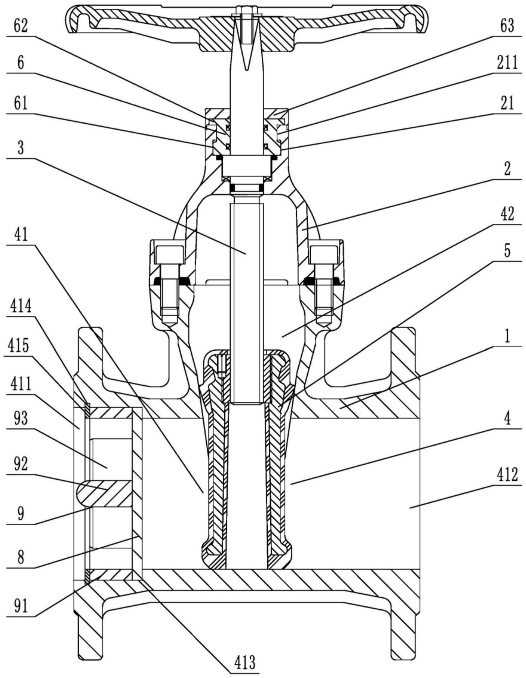
    1. A novel soft-seal gate valve comprises a valve body, a valve cover, a valve rod, a valve chamber, and a rubber-coated gate plate. The valve rod penetrates through the valve cover and is connected to the rubber-coated gate plate. The valve chamber includes a medium passage for medium circulation and a connecting chamber connected to the medium passage and corresponding to the valve cover. The rubber-coated gate plate is fitted to the connecting chamber and used to cut off or connect the medium passage. The medium passage includes an inlet end and an outlet end. The utility model is characterized in that guide rails are arranged on both sides of the rubber-coated gate plate on the inner wall of the connecting chamber, metal sliding blocks are arranged on both side walls of the rubber-coated gate plate, sliding grooves adapted to the guide rails are opened on the metal sliding blocks, a sealing groove is opened on the top of the valve cover in the axial direction relative to the valve rod, a clamping block is arranged at the opening of the sealing groove, at least three clamping blocks are arranged circumferentially at intervals relative to the central axis of the sealing groove, a sealing seat fitted to and sleeved on the valve rod is arranged inside the sealing groove, a fixed block corresponding to the rotational fit of the clamping block is arranged on the outer circumferential wall at the bottom of the sealing seat, a pressing block abutting against the top surface of the valve cover is arranged on the top of the sealing seat, and a rubber sleeve is sleeved on the top of the valve cover.

    2. A novel soft-seal gate valve according to claim 1, characterized in that a limit opening is provided at the position on the pressure block corresponding to the gap between two adjacent clamping blocks, a limit groove is provided on the end face of the pressure block, a thrust stopper is provided on the sealing seat, and the thrust stopper comprises a fixed disc adapted to the limit groove and a thrust block provided on the outer circumferential wall of the fixed disc and adapted to the limit opening.

    3. A novel soft seal gate valve according to claim 2, characterized in that a limiting block is arranged on the outer circumferential wall of the sealing seat at a position between two adjacent fixing blocks, and a clamping groove adapted to the limiting block is provided on the thrust block.

    4. A novel soft seal gate valve according to claim 1, characterized in that a stepped groove is provided in the valve body at the inlet end, and a filter screen is arranged inside the stepped groove.

    5. A novel soft-seal gate valve according to claim 4, characterized in that the side of the filter screen facing the inlet end is provided with a flow dividing device, which comprises a fixing ring that fits with interference with the inner wall of the stepped groove, a connecting column located on the central axis of the fixing ring, and a flow dividing plate connected to the fixing ring and the connecting column. The side of the stepped groove located on the inlet end facing the fixing ring is provided with an inner groove, and an elastic snap ring is arranged in the inner groove.

    6. A novel soft seal gate valve according to claim 5, characterized in that the side wall of the diverter plate facing the inlet end has a triangular cross-section.

    7. A novel soft seal gate valve according to claim 5, characterized in that one end of the connecting column facing the inlet end is hemispherical