Your location:

/ Valve products / control valve / Pneumatic Control Valve / ZMAW Pneumatic Regulating Butterfly Valve
全国销售热线:0577-67378222

Product classification of Kaiweixi

KAI WEI XI CHAN PIN FEN LEI
  • ZMAW Pneumatic Regulating Butterfly Valve

  • More Pneumatic Control Valve>>

  • More control valve>>

  • More valve>>

Contact Us
  • Phone:+86(577)6730 7899
  • Mobile:+86 195 1816 9569
  • Fax:+86(577)6738 7099
  • Email:Lucas@kaiweixi.com
  • Address:No. 1, Linxia Road, Oubei Street, Yongjia County, Wenzhou City, Zhejiang Province,china
  • Website:https://www.kaiweixi.com
Other valve products you may need
  • ZJHP Compact Pneumatic Diaphragm Single-seated Regulating Valve
  • Pneumatic Diaphragm Double-seated Straight-through Control Valve
  • ZJHPF Pneumatic Fluorine-lined Bellows Sealed Control Valve
  • ZSPQ Pneumatic Piston-type Fast Shut-off Valve
  • ZJHJ Pneumatic Angle Control Valve
ZMAW  Pneumatic  Regulating Butterfly Valve

ZMAW Pneumatic Regulating Butterfly Valve

  • Model:ZMAW-16C/ZMAW-25C/ZMAW-40C/ZMAW-16P/ZMAW-25P/ZMAW-40P
  • Specification:DN80-DN1000
  • Temperature:-20~560℃
  • Medium:Large diameter, high flow, concentrated/cloudy slurry, or boiler/kiln flue gas
  • Pressure:PN1.6、PN2.5、PN4.0
  • Connection method:Wafer
  • Driving method:Pneumatic
  • Material:Carbon steel, stainless steel
x

Add QR code to serve you!

x

Add QR code to serve you!

x

Add QR code to serve you!

x
ZMAW Pneumatic Regulating Butterfly ValveOverview

ZMAW  pneumatic  regulating butterfly valve is an industrial automation execution unit consisting of a multi-spring pneumatic diaphragm actuator and a high-performance regulating butterfly valve body. By receiving pneumatic signals from the control system (or standard 4-20mA DC signals converted via an electro-pneumatic positioner), the valve utilizes the thrust generated in the diaphragm chamber to drive the valve stem, causing the disc to rotate within a range of 0-90 degrees. This adjusts the fluid flow area in real-time to achieve continuous proportional regulation of process parameters such as flow rate, pressure, and temperature. Due to its streamlined flow path, low resistance coefficient, and compact structure, this series is particularly suitable for large-diameter, high-flow, and low-pressure-differential conditions with limited installation space, widely used in metallurgy, environmental protection, water treatment, and HVAC systems.
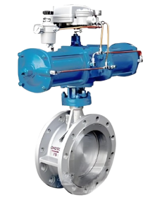
Product Image of ZMAW  Pneumatic  Regulating Butterfly Valve

ZMAW Pneumatic Regulating Butterfly ValveCharacteristic

1. Compact and lightweight design:The integrated compact design results in a significantly lower height and weight compared to same-sized single or double-seated control valves. This saves installation space and reduces mechanical loads on the pipeline.
2.High flow capacity and low resistance:The disc features a streamlined design, ensuring unobstructed flow when fully open. Its extremely low resistance coefficient provides a large flow coefficient (Kv value), offering significant energy-saving advantages in high-flow conditions.
3.Precise proportional regulation:Paired with a smart positioner, the disc rotation angle maintains an excellent proportional relationship with the control signal, providing linear or equal percentage characteristics for stable regulation across wide load variations.
4.Multiple sealing options:Available with rubber soft-sealing (bubble-tight) or metal hard-sealing (triple-offset for high temp/pressure). Precision-machined sealing pairs ensure reliable shut-off performance in the fully closed position.
5.Intrinsically safe attributes:Driven by compressed air, it involves no risk of electrical sparks, providing natural safety. It supports fail-safe modes, automatically resetting the valve to a safe position via spring force upon air supply failure.
6.Corrosion and wear resistance:The body can be rubber-lined or fluorine-lined, with the disc and bearings available in stainless steel or wear-resistant alloys. This allows the valve to handle corrosive media, slurries, and fibrous industrial waste.
7.Smooth drive and long life:The multi-spring diaphragm actuator ensures uniform force and sensitive response. Low-friction bearings in the transmission reduce operating torque and mechanical wear, ensuring long-term operational reliability.
8.Modular maintenance:The simple structure features minimal wearing parts. The scientific connection between actuator and body allows for online inspection and replacement of diaphragms or seals without removing the valve from the line, reducing costs.

ZMAW Pneumatic Regulating Butterfly Valvestructure principle

Structural Drawing of ZMAW Pneumatic  Regulating Butterfly Valve


List of Component Names and Materials

Component NameMaterial
Valve bodyCarbon steel, stainless steel
Long shaft1Cr18Ni9Ti
Inner bearingBronze, stainless steel surfacing Stellite alloy
Valve plateCarbon steel, 1Cr18Ni12Mo2Ti
Valve seatCarbon steel, stainless steel lined synthetic rubber or reinforced PTFE
PackingPTFE, flexible graphite
Valve coverCarbon steel


ZMAW Pneumatic Regulating Butterfly Valvetechnology parameter

Performance Specification Sheet


Performance Specification Sheet
Nominal Pressure1.62.54.0MPa
Strength test pressure2.43.86.0
Sealing test pressure1.762.84.4
Applicable Temperature-20-560


ZMAW Pneumatic Regulating Butterfly Valvestandard size

Standard requirements for external dimensions

1. The structural length of the valve shall comply with the standard of GB/T12221

2. Connecting flanges according to GB/T17241.6 standard


Outline Drawing of ZMAW Pneumatic  Regulating Butterfly Valve

Outline dimension table(Unit: mm)

Nominal Diameter (DN)801001502002503003504004505006007008009001000
H6357608109601116
H1435560660796
H26580100120150200
H3270295480500695
B80100140170190210250
D15017022528033539544549555060070581092010201120
N×d4-188-1812-1812-2316-2320-2524-2524-3028-30
L32137039545550559964971176181110231123125813581458
L1100114125160185212237274299324495549610660710
A282360470620


Articles related to technology research and development
  • Dynamic balance electric control valve Patent

       The utility model provides a dynamically balanced electric regulating valve, which includes a valve body, a valve cover, a valve rod, a valve core installed inside the valve body and connected to the valve rod, and an actuator installed on the valve cover and connected to the top end of the valve rod. The valve body is internally provided with a water inlet chamber, a valve cavity, and a water outlet chamber in order towards the direction of medium flow. The valve core is in the shape of a bucket with its opening facing downwards. The valve core is located inside the valve cavity and is used for connecting or cutting off between the water inlet chamber and the valve cavity. The top of the valve core is provided with a through port for medium circulation. Above the through port, there is a filter cover detachably connected to the valve core. The valve rod is provided with a step, and the outside of the step is covered with an elastic sleeve that fits it. The top of the filter cover is provided with a fixing hole that fits the elastic sleeve. This utility model can filter the medium, is simple to install, time-saving, labor-saving, and can reduce the medium pressure inside the valve body, extending the service life of the valve core.

    1. A dynamic balance electric regulating valve, comprising a valve body, a valve cover, a valve rod, a valve core installed inside the valve body and connected to the valve rod, and an actuator installed on the valve cover and connected to the top end of the valve rod. Its characteristic lies in that the valve body is sequentially provided with an inlet chamber, a valve cavity, and an outlet chamber in the direction of medium flow. The valve core is in the shape of a bucket with an opening facing downwards. The valve core is located inside the valve cavity and is used for connecting or cutting off between the inlet chamber and the valve cavity. The top of the valve core is provided with a port for medium circulation. Above the port, there is a filter cover detachably connected to the valve core. The valve rod is provided with a step, and the outside of the step is covered with an elastic sleeve that fits it. The top of the filter cover is provided with a fixing hole that fits the elastic sleeve.

    2. A dynamic balance electric regulating valve according to claim 1, characterized in that the bottom of the valve body is provided with a downward-opening groove, which is connected to the valve cavity through a through hole. A bottom cover connected to the valve body is arranged below the groove, and a pressure relief mechanism is arranged inside the groove. The pressure relief mechanism comprises a force-receiving member, a pressure plate connected to the force-receiving member, and a first spring arranged below the pressure plate and abutting against the bottom cover. The force-receiving member comprises a flow diversion block protruding from the through hole and a connecting rod connected to the flow diversion block, and the connecting rod passes through the pressure plate and is locked and fixed by a nut.

    3. A dynamic balance electric regulating valve according to claim 2, characterized in that the top end of the pressure plate is pressed against the top wall of the groove, the bottom of the pressure plate is provided with a boss, and the top end of the first spring is sleeved on the boss.

    4. A dynamic balance electric control valve according to claim 1, characterized in that the valve rod is arranged through the valve cover, a sealing cover threadedly connected to the valve cover is sleeved on the valve rod, a convex ring abutting against the valve cover is arranged on the outer circumferential wall of the sealing cover, a nut cover threadedly connected to the sealing cover is arranged at the connection between the sealing cover and the valve rod, an installation groove is arranged at the connection between the nut cover and the valve rod, a plurality of O-rings adapted to the valve rod are stacked in the installation groove, and a packing gland threadedly connected to the installation groove is arranged above the O-rings.

    5. A dynamic balance electric control valve according to claim 4, characterized in that a second spring is arranged between the packing gland and the O-ring.

    6. A dynamic balance electric control valve according to claim 5, characterized in that a sealing ring adapted to the valve rod is arranged inside the nut cover below the installation groove.

    7. A dynamic balance electric control valve according to claim 6, characterized in that the bottom of the sealing cover is provided with a thrust ring that is threadedly connected to the sealing cover and abuts against the bottom end of the valve cover.

    8. A dynamic balance electric regulating valve according to claim 1, characterized in that the top surface of the elastic sleeve is higher than the top surface of the filter cover.

    9. A dynamic balance electric control valve according to claim 8, characterized in that the filter cover is connected to the valve core through threads.