Your location:

/ Valve products / Gate valve / Hard sealed gate valve / Z61Y Forged Steel Butt-Weld Gate Valve
全国销售热线:0577-67378222

Product classification of Kaiweixi

KAI WEI XI CHAN PIN FEN LEI
  • Z61Y Forged Steel Butt-Weld Gate Valve

  • More Hard sealed gate valve>>

  • More Gate valve>>

  • More valve>>

Contact Us
  • Phone:+86(577)6730 7899
  • Mobile:+86 1815 7711 652
  • Fax:+86(577)67387099
  • Email:merry@kaiweixi.com
  • Address:No. 1, Linxia Road, Oubei Street, Yongjia County, Wenzhou City, Zhejiang Province,china
  • Website:https://www.kaiweixi.com
Other valve products you may need
  • Z41H Stainless Steel Gate Valve
  • Z41H Forged Steel Flanged Gate Valve
  • Z41W Bronze Gate Valve
  • Z941W Electric Flanged Gate Valve
  • Z641W Pneumatic Flanged Gate Valve
Z61Y Forged Steel Butt-Weld Gate Valve

Z61Y Forged Steel Butt-Weld Gate Valve

  • Model:Z61Y-16C/Z61Y-25C/Z61Y-40C/Z61Y-64C/Z61Y-100C//Z61Y-160C//Z61Y-320C/Z61Y-16P/Z61Y-25P/Z61Y-40P/Z61Y-64P/Z61Y-100P//Z61Y-160P//Z61Y-320P/Z61Y-16R/Z61Y-25R/Z61Y-40R/Z61Y-64R/Z61Y-100R//Z61Y-160R//Z61Y-320R
  • Specification:DN15-DN200
  • Temperature:-20ºC~+150ºC~425ºC~550ºC
  • Medium:Water, oils, steam, gases, and corrosive media.
  • Pressure:PN16-PN320
  • Connection method:flange connection
  • Driving method: manual, bevel gear, electric, pneumatic, hydraulic
  • Material:Forged steel, forged stainless steel
x

Add QR code to serve you!

x

Add QR code to serve you!

x

Add QR code to serve you!

x
Z61Y Forged Steel Butt-Weld Gate ValveOverview

Overview

Z61Y forged steel welded gate valve is a rising stem wedge gate valve manufactured with a forged steel valve body and welded end connection. The valve body is formed through forging process, with a dense internal structure and excellent mechanical properties. The valve is driven by a handwheel to lift and lower the valve stem, which in turn drives the wedge gate to open and close the pipeline. The sealing surface adopts hard alloy overlay welding ("Y" type) to form a high-performance metal hard seal. Prefabricated welding grooves at both ends can be directly welded to the pipeline to form a permanent, zero leakage connection. This valve is designed specifically for high temperature, high pressure, and harsh working conditions, making it an ideal choice for industries such as power plants and petrochemicals. Mainly welded and installed in the main steam system of power plant boilers, high-pressure feedwater pipelines, petrochemical hydrogenation units, synthetic ammonia process pipelines, nuclear power plant auxiliary systems, and other high-temperature and high-pressure critical pipe sections with extreme requirements for connection reliability, sealing, and pressure bearing capacity, as permanent and high safety cutoff equipment.

Z61Y Forged Steel Butt-Weld Gate Valve Product Drawing          

Z61Y Forged Steel Butt-Weld Gate ValveCharacteristic

Features

1. Forged steel valve body, excellent strength

The valve body is forged with high-quality forged steel (such as A105, F22, F304, F316), which has a dense structure, no casting defects, high mechanical strength, excellent impact resistance, and is suitable for high pressure and fatigue conditions.

2. Welding connection, absolute sealing

Both ends are equipped with standard welding grooves, which are directly welded to the pipeline to eliminate the risk of flange gasket leakage. The connection strength is high and can withstand high temperature, high pressure, and thermal stress cycles.

3. Hard alloy seal ("Y" type)

The sealing surface of the valve disc and seat is welded with high hardness alloys such as Stellite, which have high hardness, wear resistance, high temperature resistance, erosion resistance, excellent sealing performance, and long service life.

4. Clear stem structure, intuitive valve position

The valve stem rises and falls with the gate, and the valve opening can be directly determined by observing the height of the valve stem extension, which is convenient for operation and maintenance.

5. Full bore design with low flow resistance

Adopting a full bore flow channel, the medium has low flow resistance and pressure loss, making it suitable for systems with strict pressure drop requirements.

6. Suitable for extreme working conditions

The overall structure and material selection make it suitable for higher working pressures (such as PN100-PN400) and temperatures (up to 600 ℃), with stable and reliable performance.

Z61Y Forged Steel Butt-Weld Gate Valvestructure principle

Z61Y Forged Steel Butt-Weld Gate Valve Structure Diagram

Component name and material

序号No零件名称part nameCStoASTMAStoASTMSStoASTM
A105F22F304(L)F316(L)
1阀体bodyA105A182F22A182F304(L)A182F316(L)
2阀座seatA276420A276304A276304(L)A276316(L)
3闸板plateA182F430&410A182F304A182F304(L)A182F316(L)
4阀杆stemA182F6A182F304A182F304(L)A182F316(L)
5垫片gasket316夹柔性石墨 flexible graphite316夹PTFE
6阀盖coverA105A182F22A182F304(L)A182F316(L)
7螺栓BoltA193B7A193B16A193B8A193B8M
8销钉PinA276420A182F304
9填料压套Packing glandA276410A182F304(L)A182F316(L)
10活节螺栓drop boltA193B7A193B16A193B8A193B8M
11填料压板Filler pressure plateA105A182F11A182F304(L)A182F316(L)
12螺母 nutA1942HA1944A1948A1948M
13阀杆螺母stem nutA276420
14锁紧螺母 lock nurA1942HA1944A1948A1948M
15铭牌NameplateSS
16手轮hand wheelA197
17垫片gasketA473431
18填料 Filler柔性石墨 flexible graphitePTFE


Z61Y Forged Steel Butt-Weld Gate Valvetechnology parameter

Performance Specification Table

公称压力(MPa)Nominal Pressure壳体试验(MPa)Shell Test密封试验(MPa)Seal Test工作温度Working Tempe ration适用介质Suitable
1.01.51.1小于等于100度-425度纸浆、污水、煤浆、灰、渣水混和物 Mortar Mixture, Dregs With Water Proportion
1.62.41.8小于等于100度


Z61Y Forged Steel Butt-Weld Gate Valvestandard size

Z61Y Forged Steel Butt-Weld Gate Valve Outline Drawing

Outline Dimension Table

NPS缩径Diameter reduction3/8"1/2"3/4"1"11/4"11/2"2"
全径full diameter3/8"1/2"3/4"1"11/4"11/2"2"
L92111111120120140178210
H(开)169197197236246283330354
W100125125160160180200240
重量Weight螺栓式Bolt-type2.54.34.26.68.812.517.223.5
焊接式 Welding type2.44.24.06.38.712.117.222.0


Articles related to technology research and development
  • soft-sealed gate valve patented

       The utility model discloses a novel soft-seal gate valve, which includes a valve body, a valve cover, a valve rod, a valve chamber, and a rubber-coated gate plate. The valve rod penetrates through the valve cover and is connected to the rubber-coated gate plate. The valve chamber includes a medium channel for medium circulation and a connecting chamber that is connected to the medium channel and corresponds to the valve cover. The rubber-coated gate plate is adapted to the connecting chamber and used to cut off or connect the medium channel. The medium channel includes an inlet end and an outlet end. Guide rails are arranged on the inner wall of the connecting chamber on both sides opposite to the rubber-coated gate plate. Both sides of the rubber-coated gate plate are provided with metal sliders, and the metal sliders are provided with sliding grooves that are adapted to the guide rails. Compared to existing soft-seal gate valves, the utility model has good sealing performance, convenient disassembly and assembly, and a long service life for the rubber-coated gate plate.
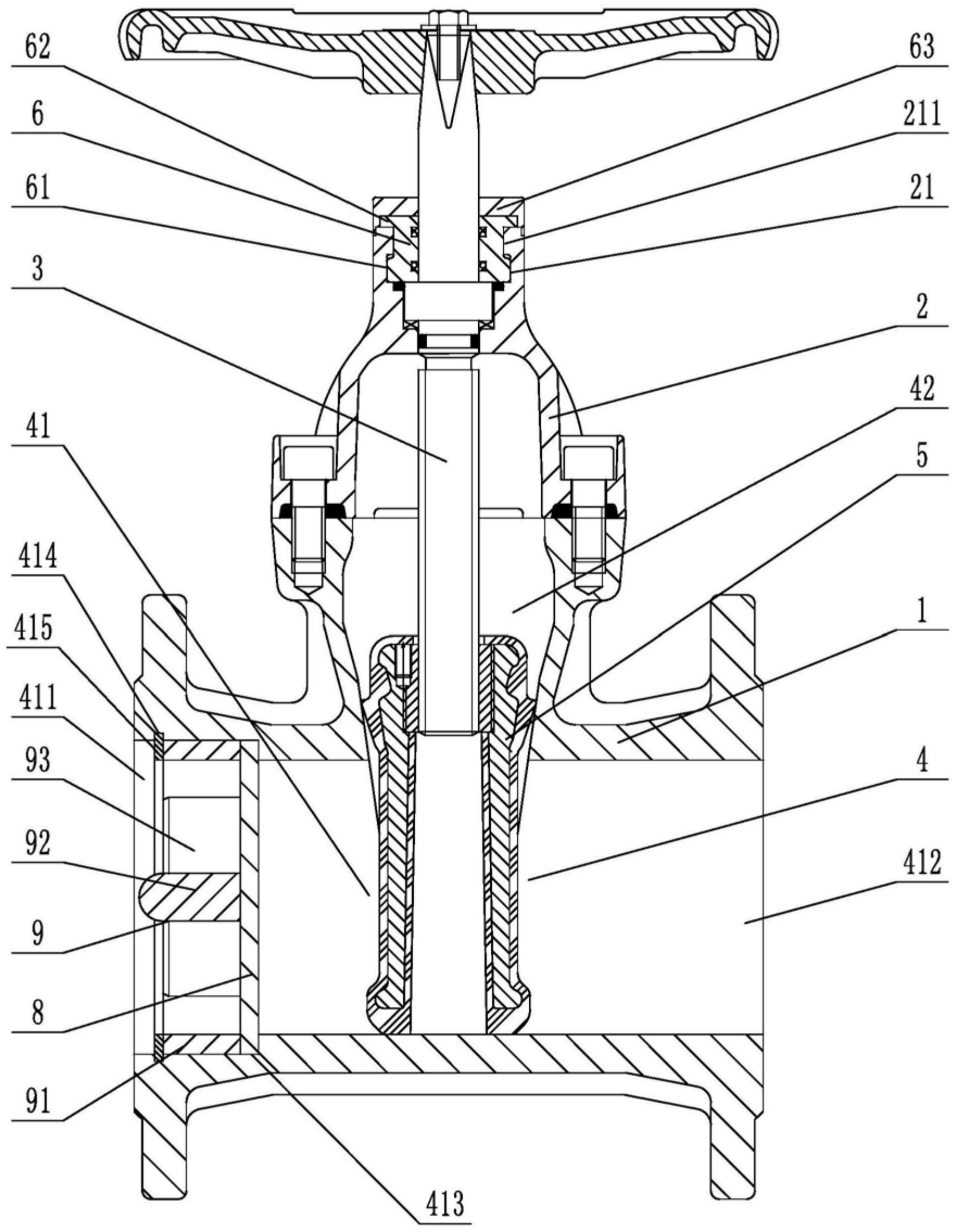
    1. A novel soft-seal gate valve comprises a valve body, a valve cover, a valve rod, a valve chamber, and a rubber-coated gate plate. The valve rod penetrates through the valve cover and is connected to the rubber-coated gate plate. The valve chamber includes a medium passage for medium circulation and a connecting chamber connected to the medium passage and corresponding to the valve cover. The rubber-coated gate plate is fitted to the connecting chamber and used to cut off or connect the medium passage. The medium passage includes an inlet end and an outlet end. The utility model is characterized in that guide rails are arranged on both sides of the rubber-coated gate plate on the inner wall of the connecting chamber, metal sliding blocks are arranged on both side walls of the rubber-coated gate plate, sliding grooves adapted to the guide rails are opened on the metal sliding blocks, a sealing groove is opened on the top of the valve cover in the axial direction relative to the valve rod, a clamping block is arranged at the opening of the sealing groove, at least three clamping blocks are arranged circumferentially at intervals relative to the central axis of the sealing groove, a sealing seat fitted to and sleeved on the valve rod is arranged inside the sealing groove, a fixed block corresponding to the rotational fit of the clamping block is arranged on the outer circumferential wall at the bottom of the sealing seat, a pressing block abutting against the top surface of the valve cover is arranged on the top of the sealing seat, and a rubber sleeve is sleeved on the top of the valve cover.

    2. A novel soft-seal gate valve according to claim 1, characterized in that a limit opening is provided at the position on the pressure block corresponding to the gap between two adjacent clamping blocks, a limit groove is provided on the end face of the pressure block, a thrust stopper is provided on the sealing seat, and the thrust stopper comprises a fixed disc adapted to the limit groove and a thrust block provided on the outer circumferential wall of the fixed disc and adapted to the limit opening.

    3. A novel soft seal gate valve according to claim 2, characterized in that a limiting block is arranged on the outer circumferential wall of the sealing seat at a position between two adjacent fixing blocks, and a clamping groove adapted to the limiting block is provided on the thrust block.

    4. A novel soft seal gate valve according to claim 1, characterized in that a stepped groove is provided in the valve body at the inlet end, and a filter screen is arranged inside the stepped groove.

    5. A novel soft-seal gate valve according to claim 4, characterized in that the side of the filter screen facing the inlet end is provided with a flow dividing device, which comprises a fixing ring that fits with interference with the inner wall of the stepped groove, a connecting column located on the central axis of the fixing ring, and a flow dividing plate connected to the fixing ring and the connecting column. The side of the stepped groove located on the inlet end facing the fixing ring is provided with an inner groove, and an elastic snap ring is arranged in the inner groove.

    6. A novel soft seal gate valve according to claim 5, characterized in that the side wall of the diverter plate facing the inlet end has a triangular cross-section.

    7. A novel soft seal gate valve according to claim 5, characterized in that one end of the connecting column facing the inlet end is hemispherical