Your location:

/ Valve products / Gate valve / Hard sealed gate valve / Z741H Hydraulic Flanged Gate Valve
全国销售热线:0577-67378222

Product classification of Kaiweixi

KAI WEI XI CHAN PIN FEN LEI
  • Z741H Hydraulic Flanged Gate Valve

  • More Hard sealed gate valve>>

  • More Gate valve>>

  • More valve>>

Contact Us
  • Phone:+86(577)6730 7899
  • Mobile:+86 1815 7711 652
  • Fax:+86(577)67387099
  • Email:merry@kaiweixi.com
  • Address:No. 1, Linxia Road, Oubei Street, Yongjia County, Wenzhou City, Zhejiang Province,china
  • Website:https://www.kaiweixi.com
Other valve products you may need
  • Z41H Stainless Steel Gate Valve
  • Z61Y Forged Steel Butt-Weld Gate Valve
  • Z41H Forged Steel Flanged Gate Valve
  • Z41W Bronze Gate Valve
  • Z941W Electric Flanged Gate Valve
Z741H Hydraulic Flanged Gate Valve

Z741H Hydraulic Flanged Gate Valve

  • Model:Z741H-16C/Z741H-25C/Z741H-40C/Z741H-64C/Z741H-16P/Z741H-25P/Z741H-40P/Z741H-64P/Z741H-16R/Z741H-25R/Z741H-40R/Z741H-64R
  • Specification:DN50-DN300
  • Temperature:≤425 ℃
  • Medium:Water, oils, steam, gases, and corrosive media.
  • Pressure:PN16-PN64
  • Connection method:flange
  • Driving method:hydraulic
  • Material:Cast steel, stainless steel
x

Add QR code to serve you!

x

Add QR code to serve you!

x

Add QR code to serve you!

x
Z741H Hydraulic Flanged Gate ValveOverview

Z741H hydraulic gate valve is a rising stem wedge gate valve driven by hydraulic actuator and connected by flange. It drives the piston or cylinder through hydraulic oil to lift the valve stem, causing the wedge gate to move vertically and achieve the opening and closing of the pipeline. The valve sealing surface is welded with alloy steel ("H" type) to form a metal hard seal. This valve integrates a manual operating mechanism for emergency operation in case of hydraulic system failure. It is designed specifically for high thrust, high reliability, and remote automation control applications and is an ideal execution unit in hydraulic control systems for industries such as metallurgy, mining, and power. Widely used in hydraulic control systems in industries such as metallurgy (blast furnaces, converters), mining (slurry transportation), power (boiler feedwater), petrochemicals, water conservancy, and heavy machinery, as a key cutting device for large-diameter, high-pressure differential pipelines. Especially suitable for situations that require high thrust drive, frequent operation, and remote automation control.

Z741H Hydraulic Flanged Gate Valve  Product Drawing

Z741H Hydraulic Flanged Gate ValveCharacteristic

1. Hydraulic drive, strong thrust

Equipped with hydraulic cylinder actuator, powered by hydraulic oil, it has high output thrust and smooth opening and closing, especially suitable for gate valve operation under large diameter and high pressure difference conditions.

2. Clear stem structure, intuitive valve position

The valve stem rises and falls with the gate, and the valve opening can be directly determined by observing the height of the valve stem extension, which is convenient for on-site inspection and debugging.

3. Alloy steel hard seal ("H" type)

The sealing surface of the valve disc and seat is welded with alloy steel (such as 13Cr, Stellite), which has high hardness, wear resistance, erosion resistance, reliable sealing, and long service life.

4. Flange connection, stable and reliable

Using standard flange connections (such as RF flanges), the connection strength is high, the sealing performance is good, and it is easy to install and disassemble.

5. Manual emergency operation

The top or side of the hydraulic cylinder is equipped with a manual pump or handwheel mechanism, which can be manually operated in case of hydraulic system failure or debugging, ensuring that the system is controllable in any situation.

6. Remote automation control

It can be integrated with hydraulic control systems, receive electrical signals for remote automatic control, and is suitable for automation systems that require centralized monitoring or process interlocking.

7. Pressure holding and locking function

The hydraulic system can be equipped with pressure maintaining valves or locking devices to keep the valve position unchanged in case of pressure loss, preventing accidental action.

Z741H Hydraulic Flanged Gate Valvestructure principle

Part name and material list

阀体、阀盖闸板、阀座 Body,Bonnet,Gate Plate,Seat阀杆 Stem阀杆螺母填料 Stem Nut &Packing手轮 Handwheel
碳素钢 Carbon Steel优质碳钢 + 硬质合金或不锈钢 High-quality Carbon Steel + Hard Alloy or Stainless Steel铝青铜、石墨石棉盘根 Aluminum Bronze,Graphite Asbestos Packing可锻铸铁 Malleable Cast Iron
铬镍钛钢 Cr-Ni-Ti Steel不锈钢、不锈钢 + 硬质合金 Stainless Steel/Stainless Steel + Hard Alloy铬镍钛不锈钢、铝青铜、聚四氟乙烯 Cr-Ni-Ti Stainless Steel,Aluminum Bronze,PTFE可锻铸铁 Malleable Cast Iron
铬镍钼钛不锈钢 Cr-Ni-Mo-Ti Stainless Steel不锈钢、不锈钢 + 硬质合金 Stainless Steel/Stainless Steel + Hard Alloy铬镍钛不锈钢、铝青铜、烯石棉盘根 Cr-Ni-Ti Stainless Steel,Aluminum Bronze,Asbestos Packing可锻铸铁 Malleable Cast Iron
铬钼钢 Cr-Mo Steel合金钢 + 硬质合金 Alloy Steel + Hard Alloy铬钼铝钢、铝青铜、柔性石墨 Cr-Mo-Al Steel,Aluminum Bronze,Flexible Graphite可锻铸铁 Malleable Cast Iron


Z741H Hydraulic Flanged Gate Valvetechnology parameter

Performance Specification Sheet

公称压力 Nominal PressurePN PN
壳体试验 Shell Test1.5 Mpa 1.5 Mpa
密封试验 Seal Test1.1 Mpa 1.1 Mpa
工作温度 Operating Temperature橡胶≤80℃ 四氟密封≤180℃ 硬密封≤425℃ Rubber ≤80℃,PTFE seal ≤180℃,Metal seal ≤425℃
适用介质 Suitable Medium糖浆、纸浆、污水、煤浆、灰、渣水混合物 Syrup,pulp,sewage,coal slurry,ash,slag water mixture


Z741H Hydraulic Flanged Gate Valvestandard size

Outline Drawing of Z741H Hydraulic Flanged Gate Valve

Outline Dimension Table

MPaDNLDD1D2HN-MD0
1.050431601251003304-M16180
65461801451203604-M16180
80461951601353904-M16220
100522151801554408-M16220
125562452101855108-M16230
150562802402106008-M20280
200603352952657008-M20360
2506839035032084012-M20360
3007844040036896012-M20400
35078500460428111016-M20400
400102565515482125016-M22400
450114615565532138020-M22530
500127670620585153020-M22530
600154780725685180020-M27600
700165895840800215024-M27600
8001901010950898242024-M30680
900203111010501005268028-M30680
1000216122011601115310028-M30700
1200254145013801325345032-M36800
1.65043160125993304-M16180
65461851451203604-M16180
80462001601353908-M16220
100522201801554408-M16220
125562502101855108-M16230
150562852402106008-M20280
2006034029526570012-M20360
2506840535531084012-M22360
3007846041037596012-M22400
35078520470435111016-M22400
400102580525485125016-M27400
450114640585545138020-M27530
500127715650609153020-M30530
600154840770720180020-M36600
700165910840788215024-M36600
8001901025950898242024-M36680
90020311251050998268028-M36680
1000216125511701110310028-M42700


Articles related to technology research and development
  • soft-sealed gate valve patented

       The utility model discloses a novel soft-seal gate valve, which includes a valve body, a valve cover, a valve rod, a valve chamber, and a rubber-coated gate plate. The valve rod penetrates through the valve cover and is connected to the rubber-coated gate plate. The valve chamber includes a medium channel for medium circulation and a connecting chamber that is connected to the medium channel and corresponds to the valve cover. The rubber-coated gate plate is adapted to the connecting chamber and used to cut off or connect the medium channel. The medium channel includes an inlet end and an outlet end. Guide rails are arranged on the inner wall of the connecting chamber on both sides opposite to the rubber-coated gate plate. Both sides of the rubber-coated gate plate are provided with metal sliders, and the metal sliders are provided with sliding grooves that are adapted to the guide rails. Compared to existing soft-seal gate valves, the utility model has good sealing performance, convenient disassembly and assembly, and a long service life for the rubber-coated gate plate.
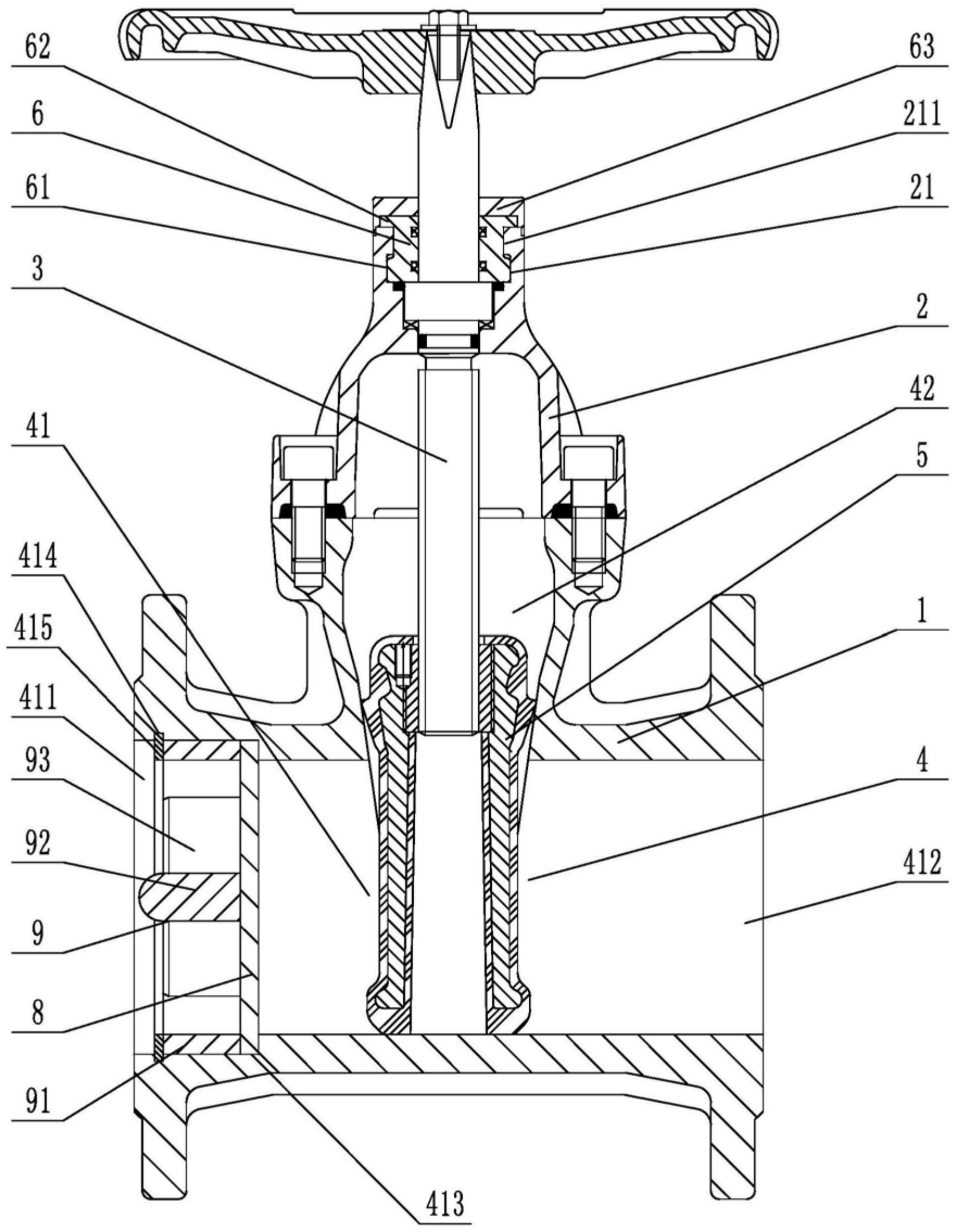
    1. A novel soft-seal gate valve comprises a valve body, a valve cover, a valve rod, a valve chamber, and a rubber-coated gate plate. The valve rod penetrates through the valve cover and is connected to the rubber-coated gate plate. The valve chamber includes a medium passage for medium circulation and a connecting chamber connected to the medium passage and corresponding to the valve cover. The rubber-coated gate plate is fitted to the connecting chamber and used to cut off or connect the medium passage. The medium passage includes an inlet end and an outlet end. The utility model is characterized in that guide rails are arranged on both sides of the rubber-coated gate plate on the inner wall of the connecting chamber, metal sliding blocks are arranged on both side walls of the rubber-coated gate plate, sliding grooves adapted to the guide rails are opened on the metal sliding blocks, a sealing groove is opened on the top of the valve cover in the axial direction relative to the valve rod, a clamping block is arranged at the opening of the sealing groove, at least three clamping blocks are arranged circumferentially at intervals relative to the central axis of the sealing groove, a sealing seat fitted to and sleeved on the valve rod is arranged inside the sealing groove, a fixed block corresponding to the rotational fit of the clamping block is arranged on the outer circumferential wall at the bottom of the sealing seat, a pressing block abutting against the top surface of the valve cover is arranged on the top of the sealing seat, and a rubber sleeve is sleeved on the top of the valve cover.

    2. A novel soft-seal gate valve according to claim 1, characterized in that a limit opening is provided at the position on the pressure block corresponding to the gap between two adjacent clamping blocks, a limit groove is provided on the end face of the pressure block, a thrust stopper is provided on the sealing seat, and the thrust stopper comprises a fixed disc adapted to the limit groove and a thrust block provided on the outer circumferential wall of the fixed disc and adapted to the limit opening.

    3. A novel soft seal gate valve according to claim 2, characterized in that a limiting block is arranged on the outer circumferential wall of the sealing seat at a position between two adjacent fixing blocks, and a clamping groove adapted to the limiting block is provided on the thrust block.

    4. A novel soft seal gate valve according to claim 1, characterized in that a stepped groove is provided in the valve body at the inlet end, and a filter screen is arranged inside the stepped groove.

    5. A novel soft-seal gate valve according to claim 4, characterized in that the side of the filter screen facing the inlet end is provided with a flow dividing device, which comprises a fixing ring that fits with interference with the inner wall of the stepped groove, a connecting column located on the central axis of the fixing ring, and a flow dividing plate connected to the fixing ring and the connecting column. The side of the stepped groove located on the inlet end facing the fixing ring is provided with an inner groove, and an elastic snap ring is arranged in the inner groove.

    6. A novel soft seal gate valve according to claim 5, characterized in that the side wall of the diverter plate facing the inlet end has a triangular cross-section.

    7. A novel soft seal gate valve according to claim 5, characterized in that one end of the connecting column facing the inlet end is hemispherical