Your location:

/ Valve products / Gate valve / API, JIS, DIN, GOST Gate Valve / BS Standard Rising Stem Metal-Seated Gate Valve
全国销售热线:0577-67378222

Product classification of Kaiweixi

KAI WEI XI CHAN PIN FEN LEI
  • BS Standard Rising Stem Metal-Seated Gate Valve

  • More API, JIS, DIN, GOST Gate Valve>>

  • More Gate valve>>

  • More valve>>

Contact Us
  • Phone:+86(577)6730 7899
  • Mobile:+86 1815 7711 652
  • Fax:+86(577)67387099
  • Email:merry@kaiweixi.com
  • Address:No. 1, Linxia Road, Oubei Street, Yongjia County, Wenzhou City, Zhejiang Province,china
  • Website:https://www.kaiweixi.com
Other valve products you may need
  • Z41W-150LB API Standard Gate Valve (150LB Pressure Class)
  • Z43W Stainless Steel Metal Seated Parallel Slide Gate Valve
  • API Standard Bevel Gear Gate Valve
  • Z543Y Parallel Slide Gate Valve with Hardfaced Seats
  • Z41H-10K Stainless Steel Gate Valve (JIS 10K Standard)
BS Standard Rising Stem Metal-Seated Gate Valve

BS Standard Rising Stem Metal-Seated Gate Valve

  • Model:Z41T-150LB/Z41T-300LB/Z41T-600LB/Z41H-150LB/Z41H-300LB/Z41H-600LB
  • Specification:DN50-DN600
  • Temperature:-10℃-120℃
  • Medium:water, oil, steam, gas, and corrosive media.
  • Pressure:150LB-600LB
  • Connection method:flange
  • Driving method:manual
  • Material:ductile iron, cast steel, stainless steel
x

Add QR code to serve you!

x

Add QR code to serve you!

x

Add QR code to serve you!

x
BS Standard Rising Stem Metal-Seated Gate ValveOverview

The BS hard seal gate valve is a concealed wedge gate valve designed and manufactured strictly in accordance with British Standards (BS). The valve stem is located inside the valve body and only rotates during opening and closing without lifting, with a constant structural height. The sealing surface adopts a metal to metal hard sealing structure (such as alloy steel or stainless steel) to form a reliable hard sealing pair. The valve connection end complies with the British standard flange standards (such as BS 4504, BS 10) and is suitable for pipeline systems that follow the British standard system. This valve is designed specifically for medium to high pressure, high temperature, and wear-resistant working conditions, and is an ideal choice for Commonwealth countries and engineering projects that adopt British standard design. Widely used in municipal water supply, sewage treatment, petrochemicals, electricity, ships, and industrial pipeline systems in Commonwealth countries, especially suitable for engineering projects designed with British standards. Commonly used as a reliable cutoff device for medium and high pressure pipelines transporting water, steam, oil, gas, and weakly corrosive media. Widely used in municipal water supply, sewage treatment, petrochemicals, electricity, ships, and industrial pipeline systems in Commonwealth countries, especially suitable for engineering projects designed with British standards. Commonly used for transporting water, steam, oil, gas, and weakly corrosive media in medium and high pressure pipelines, as a key cutting device that requires intuitive display of opening, easy monitoring, and maintenance.

BS Standard Rising Stem Metal-Seated Gate Valve  Product Drawing

BS Standard Rising Stem Metal-Seated Gate ValveCharacteristic

1. Compliant with British standard specifications

The design, dimensions, testing, and acceptance strictly follow British standards (such as BS 5163, BS 3464, BS 4504), and the pressure rating, structural length, and flange size fully comply with British standard requirements, ensuring international universality and compliance.

2. Clear stem structure, intuitive valve position

The valve stem rises and falls with the gate, and the operator can accurately determine the valve opening by observing the height of the valve stem extension, which facilitates system process control and safety management.

3. Metal hard seal (hard seal)

The sealing surface of the valve disc and seat is made of alloy steel (such as 13Cr) or stainless steel with welding/hardening treatment, which has high hardness, wear resistance, erosion resistance, and high temperature resistance. It is suitable for steam, hot water, oil, and particulate media, and has a long service life.

4. British standard flange connection

The connection end shall comply with BS 4504 or BS 10 standard flanges (such as PN10/16/25, Table D/E/F), and the sealing surface shall be flat or protruding, which is perfectly compatible with British standard piping systems.

5. Full bore design with low flow resistance

Adopting a full bore flow channel, the medium has low flow resistance and pressure loss, making it suitable for high flow conveying systems.

6. The valve stem seal is reliable and can be maintained online

The valve stem seal adopts multi-layer packing or formed packing, and is equipped with an upper sealing structure. When the valve is fully open, the packing can be replaced online without disassembling the valve for easy maintenance.

BS Standard Rising Stem Metal-Seated Gate Valvestructure principle

BS Standard Rising Stem Metal-Seated Gate Valve Structure Diagram、

Parts Name and Material List

序号 NO.零件名称 Parts Name材料 Material
1阀体 Body铸铁 Cast Iron
2阀座 Seat黄铜 Brass
3闸板 Wedge Disc铸铁 + 黄铜 Cast Iron+Brass
4阀杆 Stem不锈钢 Stainless Steel
5螺栓 Bolt碳钢 Carbon Steel
6螺母 Nut碳钢 Carbon Steel
7垫片 Gasket石墨 Graphite
8阀盖 Bonnet铸铁 Cast Iron
9填料 Packing石墨 Graphite
10压盖 Gland铸铁 Cast Iron
11螺栓 Bolt碳钢 Carbon Steel
12螺母 Nut碳钢 Carbon Steel
13阀杆螺母 Stem Nut黄铜 Brass
14手轮 Handwheel铸铁 Cast Iron
15手轮螺母 Clock Nut铸铁 Cast Iron


BS Standard Rising Stem Metal-Seated Gate Valvetechnology parameter

Performance Specification Sheet

性能规范表 Performance Specification Sheet
公称压力 Nominal pressure1.6MPa
强度试验压力 Strength test pressure2.4
密封试验压力Seal test pressure1.76
适用温度 Applicable temperature≤80


BS Standard Rising Stem Metal-Seated Gate Valvestandard size

Outline Drawing of BS Standard Rising Stem Metal-Seated Gate Valve

Outline Dimension Table

DIMENSIONS(mm)外形尺寸
DNLDD1HbZ- f dD0
50178152114365204-17.5180
65190165127418204-17.5180
80203185146472224-17.5200
100229216177.8550224-17.5200
125254254209.5660248-17.5240
150267280235738248-17.5240
200292336292975268-17.5320
250330406355.51128288-22320
300356457406.513352812-22400


Articles related to technology research and development
  • soft-sealed gate valve patented

       The utility model discloses a novel soft-seal gate valve, which includes a valve body, a valve cover, a valve rod, a valve chamber, and a rubber-coated gate plate. The valve rod penetrates through the valve cover and is connected to the rubber-coated gate plate. The valve chamber includes a medium channel for medium circulation and a connecting chamber that is connected to the medium channel and corresponds to the valve cover. The rubber-coated gate plate is adapted to the connecting chamber and used to cut off or connect the medium channel. The medium channel includes an inlet end and an outlet end. Guide rails are arranged on the inner wall of the connecting chamber on both sides opposite to the rubber-coated gate plate. Both sides of the rubber-coated gate plate are provided with metal sliders, and the metal sliders are provided with sliding grooves that are adapted to the guide rails. Compared to existing soft-seal gate valves, the utility model has good sealing performance, convenient disassembly and assembly, and a long service life for the rubber-coated gate plate.
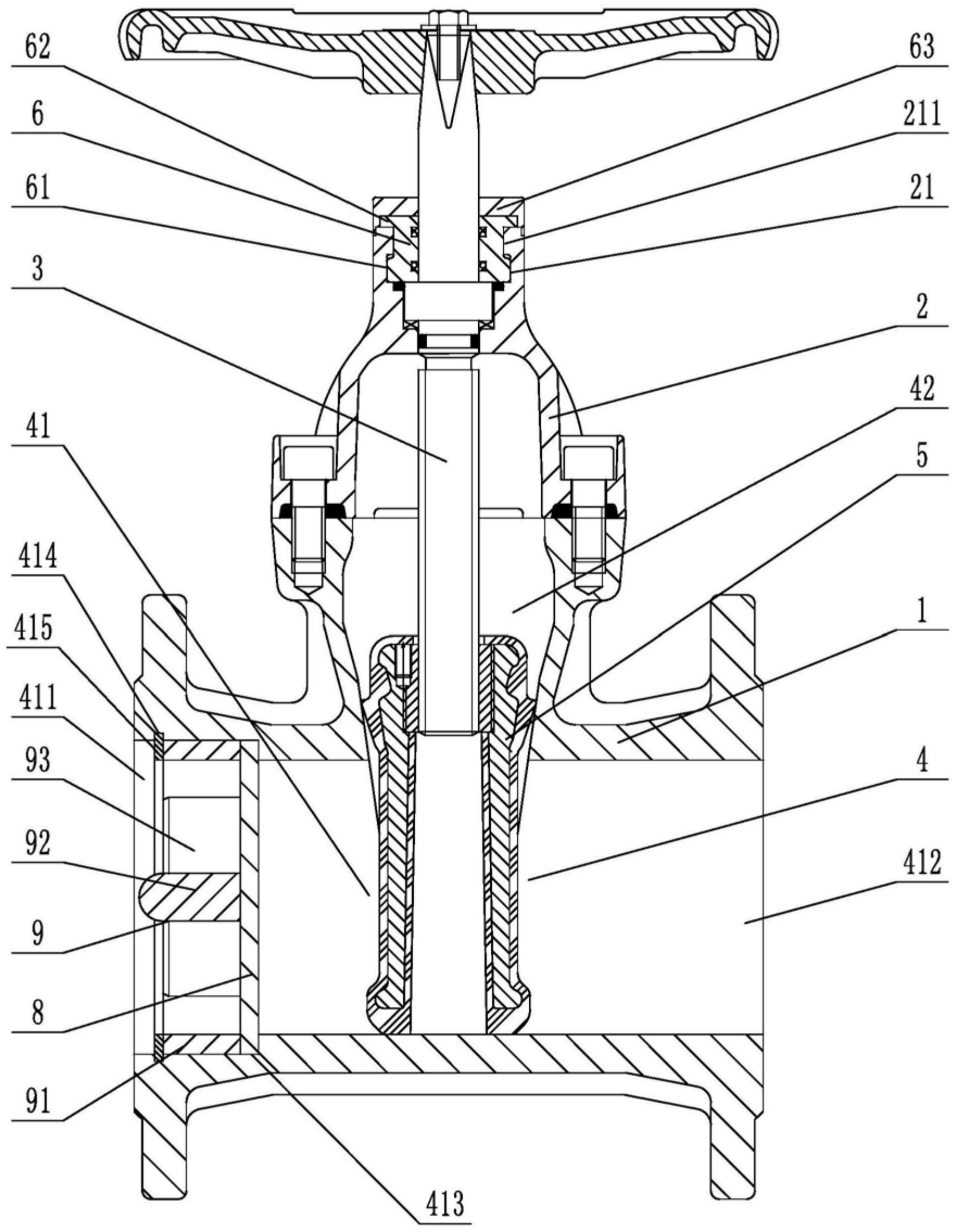
    1. A novel soft-seal gate valve comprises a valve body, a valve cover, a valve rod, a valve chamber, and a rubber-coated gate plate. The valve rod penetrates through the valve cover and is connected to the rubber-coated gate plate. The valve chamber includes a medium passage for medium circulation and a connecting chamber connected to the medium passage and corresponding to the valve cover. The rubber-coated gate plate is fitted to the connecting chamber and used to cut off or connect the medium passage. The medium passage includes an inlet end and an outlet end. The utility model is characterized in that guide rails are arranged on both sides of the rubber-coated gate plate on the inner wall of the connecting chamber, metal sliding blocks are arranged on both side walls of the rubber-coated gate plate, sliding grooves adapted to the guide rails are opened on the metal sliding blocks, a sealing groove is opened on the top of the valve cover in the axial direction relative to the valve rod, a clamping block is arranged at the opening of the sealing groove, at least three clamping blocks are arranged circumferentially at intervals relative to the central axis of the sealing groove, a sealing seat fitted to and sleeved on the valve rod is arranged inside the sealing groove, a fixed block corresponding to the rotational fit of the clamping block is arranged on the outer circumferential wall at the bottom of the sealing seat, a pressing block abutting against the top surface of the valve cover is arranged on the top of the sealing seat, and a rubber sleeve is sleeved on the top of the valve cover.

    2. A novel soft-seal gate valve according to claim 1, characterized in that a limit opening is provided at the position on the pressure block corresponding to the gap between two adjacent clamping blocks, a limit groove is provided on the end face of the pressure block, a thrust stopper is provided on the sealing seat, and the thrust stopper comprises a fixed disc adapted to the limit groove and a thrust block provided on the outer circumferential wall of the fixed disc and adapted to the limit opening.

    3. A novel soft seal gate valve according to claim 2, characterized in that a limiting block is arranged on the outer circumferential wall of the sealing seat at a position between two adjacent fixing blocks, and a clamping groove adapted to the limiting block is provided on the thrust block.

    4. A novel soft seal gate valve according to claim 1, characterized in that a stepped groove is provided in the valve body at the inlet end, and a filter screen is arranged inside the stepped groove.

    5. A novel soft-seal gate valve according to claim 4, characterized in that the side of the filter screen facing the inlet end is provided with a flow dividing device, which comprises a fixing ring that fits with interference with the inner wall of the stepped groove, a connecting column located on the central axis of the fixing ring, and a flow dividing plate connected to the fixing ring and the connecting column. The side of the stepped groove located on the inlet end facing the fixing ring is provided with an inner groove, and an elastic snap ring is arranged in the inner groove.

    6. A novel soft seal gate valve according to claim 5, characterized in that the side wall of the diverter plate facing the inlet end has a triangular cross-section.

    7. A novel soft seal gate valve according to claim 5, characterized in that one end of the connecting column facing the inlet end is hemispherical