Your location:

/ Valve products / control valve / Electric Control Valve / ZZG Electric High-Temperature and High-Pressure Wedge Gate Valve
全国销售热线:0577-67378222

Product classification of Kaiweixi

KAI WEI XI CHAN PIN FEN LEI
  • ZZG Electric High-Temperature and High-Pressure Wedge Gate Valve

  • More Electric Control Valve>>

  • More control valve>>

  • More valve>>

Contact Us
  • Phone:+86(577)6730 7899
  • Mobile:+86 195 1816 9569
  • Fax:+86(577)6738 7099
  • Email:Lucas@kaiweixi.com
  • Address:No. 1, Linxia Road, Oubei Street, Yongjia County, Wenzhou City, Zhejiang Province,china
  • Website:https://www.kaiweixi.com
Other valve products you may need
  • ZAZM Electric Compact Cage Guided Control Valve
  • VK Ultra-Compact Electric Control Valve
  • ZDLP Electronic Electric Straight-through Single-seated Control Valve
  • ZDLQ Electronic Electric Three-way Mixing Control Valve
  • ZDLP Series Electronic Electric Single-Seated Control Valve
ZZG Electric High-Temperature and High-Pressure Wedge Gate Valve

ZZG Electric High-Temperature and High-Pressure Wedge Gate Valve

  • Model:ZZG-16C/ZZG-25C/ZZG-40C/ZZG-64C/ZZG-16P/ZZG-25P/ZZG-40P/ZZG-64P/ZZG-16R/ZZG-25R/ZZG-40R/ZZG-64R
  • Specification:DN50~600
  • Temperature:-30~560℃
  • Medium:Shut-off of high-temperature and high-pressure media such as steam, water, and petroleum
  • Pressure:PN1.6~6.4MPa
  • Connection method:Flange
  • Driving method:Electric
  • Material:Cast Steel,Stainless Steel,Duplex Stainless Steel
x

Add QR code to serve you!

x

Add QR code to serve you!

x

Add QR code to serve you!

x
ZZG Electric High-Temperature and High-Pressure Wedge Gate ValveOverview

ZZG series electric high-temperature and high-pressure wedge gate valve is a high-end industrial isolation device widely used in thermal power plants, petrochemicals, and metallurgical systems. This valve consists of a high-torque multi-turn electric actuator and a high-strength wedge gate valve body. Its core design utilizes the mechanical wedging force of the wedge-shaped gate to achieve a tight bi-directional seal under extreme temperature and pressure environments. Controlled by system commands, the actuator drives the stem and gate in a vertical reciprocating motion to achieve automated opening and closing of steam, hot water, and oil pipelines. With its superior pressure-bearing capacity and erosion resistance, the ZZG series is a critical isolation component for ensuring the long-term operation of high-load systems.

Product Image of ZZG Electric High-Temperature and High-Pressure Wedge Gate Valve

ZZG Electric High-Temperature and High-Pressure Wedge Gate ValveCharacteristic

1.Wedge gate for self-tightening seal:Utilizes a flexible wedge gate structure that combines mechanical wedging force with medium pressure compensation, ensuring zero leakage under extreme differential pressures and preventing seat scoring.
2.Alloy structure for extreme temperature and pressure:The body is made of premium cast steel or Cr-Mo alloy steel with sufficient wall thickness to withstand temperatures up to 560°C and pressures up to 16.0MPa.
3.Hard alloy sealing surfaces:The gate and seat sealing faces are hard-faced with Stellite cobalt-based alloy, providing excellent hot hardness and wear resistance against high-temperature steam erosion and scaling.
4.Powerful and reliable electric drive:Equipped with high-performance multi-turn electric actuators providing high torque and self-locking capabilities. Supports remote DCS control and local manual override for accurate response.
5.Optimized full-bore flow path:The full-bore design ensures minimal resistance to the medium, with a resistance coefficient similar to a straight pipe of the same diameter, significantly reducing system pressure drop and energy loss.
6.Double seal for enhanced safety:The stem seal uses high-performance flexible graphite packing and is equipped with a back-seat structure, ensuring zero external leakage and allowing for emergency packing replacement under pressure.
7.Intelligent protection and feedback:The actuator features built-in overload protection, torque sensing, and stroke limits. Accurate valve position feedback signals facilitate integration into complex industrial logic interlock systems.
8.Standardized design for easy maintenance:Manufactured according to international valve standards with high component interchangeability. Modular layout of wearing parts simplifies on-site inspection and routine maintenance tasks.

ZZG Electric High-Temperature and High-Pressure Wedge Gate Valvestructure principle

Structural Drawing of  ZZG Electric High-Temperature and High-Pressure Wedge Gate Valve


List of Component Names and Materials

Body & BonnetDisc & SeatStemStem NutPackingHandwheel
Carbon SteelHigh-quality carbon steel + Hard alloy or Stainless steelChromium stainless steelAluminum bronzeGraphite asbestos packingMalleable cast iron
Cr-Ni-Ti SteelStainless steel, Stainless steel + Hard alloyCr-Ni-Ti stainless steelAluminum bronzePTFE impregnated packingMalleable cast iron
Cr-Ni-Mo-Ti SteelStainless steel, Stainless steel + Hard alloyCr-Ni-Mo-Ti stainless steelAluminum bronzePTFE impregnated packingMalleable cast iron
Cr-Mo SteelAlloy steel + Hard alloyCr-Mo-Al steelAluminum bronzeFlexible asbestos + 33.4Malleable cast iron


ZZG Electric High-Temperature and High-Pressure Wedge Gate Valvetechnology parameter

Performance Specification Sheet


Performance Specification Sheet
Nominal Pressure1.62.54.06.4MPa
Strength test pressure2.43.86.09.6
Sealing test pressure1.762.84.47.04
Applicable Temperature-30~+560


ZZG Electric High-Temperature and High-Pressure Wedge Gate Valvestandard size

Standard requirements for external dimensions

1. The structural length of the valve shall comply with the standard of GB/T12221

2. Connecting flanges according to GB/T17241.6 standard


Outline Drawing of  ZZG Electric High-Temperature and High-Pressure Wedge Gate Valve

Outline dimension table(Unit:mm)

Nominal Diameter DNLL1H (1.6-16 MPa)H1 (1.6-16 MPa)L2H (1.6-16 MPa)H1 (1.6-16 MPa)H (1.6-16 MPa High Temp)H1 (1.6-16 MPa High Temp)H (1.6-16 MPa)H1 (1.6-16 MPa)H (1.6-16 MPa High Temp)H1 (1.6-16 MPa High Temp)Desuperheating Water Pipe Diameter CI
503001505202005658002001030200800260103026010
653401705402156508902151040215890285104028510
803801905552256509102251060225910305106030520
1004002155802508009502501100250950330110033020
1254302256202858009902851140285990380114038032
150450230650330800109033012403301090410124041032
200500260790355800116035513103551160435131043532
250550285850390800123039013803901230470138047032
300750295940480900137048015704801370580157058032
350850445990550900145055016505501450660165066040
40095055011207001000157070017707001570800177080050
50011306801660820100017808201980820-----


Articles related to technology research and development
  • Dynamic balance electric control valve Patent

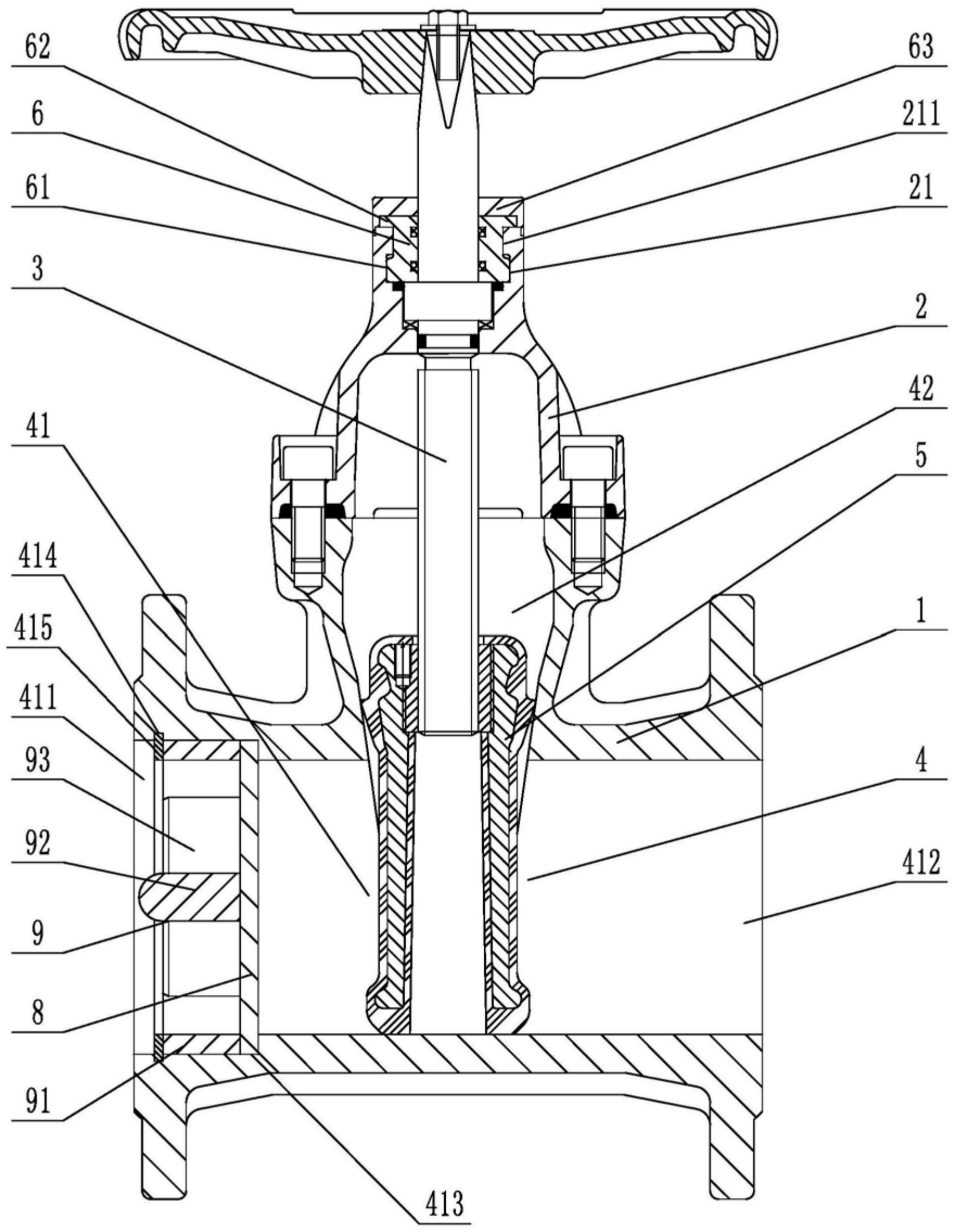
       The utility model provides a dynamically balanced electric regulating valve, which includes a valve body, a valve cover, a valve rod, a valve core installed inside the valve body and connected to the valve rod, and an actuator installed on the valve cover and connected to the top end of the valve rod. The valve body is internally provided with a water inlet chamber, a valve cavity, and a water outlet chamber in order towards the direction of medium flow. The valve core is in the shape of a bucket with its opening facing downwards. The valve core is located inside the valve cavity and is used for connecting or cutting off between the water inlet chamber and the valve cavity. The top of the valve core is provided with a through port for medium circulation. Above the through port, there is a filter cover detachably connected to the valve core. The valve rod is provided with a step, and the outside of the step is covered with an elastic sleeve that fits it. The top of the filter cover is provided with a fixing hole that fits the elastic sleeve. This utility model can filter the medium, is simple to install, time-saving, labor-saving, and can reduce the medium pressure inside the valve body, extending the service life of the valve core.

    1. A dynamic balance electric regulating valve, comprising a valve body, a valve cover, a valve rod, a valve core installed inside the valve body and connected to the valve rod, and an actuator installed on the valve cover and connected to the top end of the valve rod. Its characteristic lies in that the valve body is sequentially provided with an inlet chamber, a valve cavity, and an outlet chamber in the direction of medium flow. The valve core is in the shape of a bucket with an opening facing downwards. The valve core is located inside the valve cavity and is used for connecting or cutting off between the inlet chamber and the valve cavity. The top of the valve core is provided with a port for medium circulation. Above the port, there is a filter cover detachably connected to the valve core. The valve rod is provided with a step, and the outside of the step is covered with an elastic sleeve that fits it. The top of the filter cover is provided with a fixing hole that fits the elastic sleeve.

    2. A dynamic balance electric regulating valve according to claim 1, characterized in that the bottom of the valve body is provided with a downward-opening groove, which is connected to the valve cavity through a through hole. A bottom cover connected to the valve body is arranged below the groove, and a pressure relief mechanism is arranged inside the groove. The pressure relief mechanism comprises a force-receiving member, a pressure plate connected to the force-receiving member, and a first spring arranged below the pressure plate and abutting against the bottom cover. The force-receiving member comprises a flow diversion block protruding from the through hole and a connecting rod connected to the flow diversion block, and the connecting rod passes through the pressure plate and is locked and fixed by a nut.

    3. A dynamic balance electric regulating valve according to claim 2, characterized in that the top end of the pressure plate is pressed against the top wall of the groove, the bottom of the pressure plate is provided with a boss, and the top end of the first spring is sleeved on the boss.

    4. A dynamic balance electric control valve according to claim 1, characterized in that the valve rod is arranged through the valve cover, a sealing cover threadedly connected to the valve cover is sleeved on the valve rod, a convex ring abutting against the valve cover is arranged on the outer circumferential wall of the sealing cover, a nut cover threadedly connected to the sealing cover is arranged at the connection between the sealing cover and the valve rod, an installation groove is arranged at the connection between the nut cover and the valve rod, a plurality of O-rings adapted to the valve rod are stacked in the installation groove, and a packing gland threadedly connected to the installation groove is arranged above the O-rings.

    5. A dynamic balance electric control valve according to claim 4, characterized in that a second spring is arranged between the packing gland and the O-ring.

    6. A dynamic balance electric control valve according to claim 5, characterized in that a sealing ring adapted to the valve rod is arranged inside the nut cover below the installation groove.

    7. A dynamic balance electric control valve according to claim 6, characterized in that the bottom of the sealing cover is provided with a thrust ring that is threadedly connected to the sealing cover and abuts against the bottom end of the valve cover.

    8. A dynamic balance electric regulating valve according to claim 1, characterized in that the top surface of the elastic sleeve is higher than the top surface of the filter cover.

    9. A dynamic balance electric control valve according to claim 8, characterized in that the filter cover is connected to the valve core through threads.