Your location:

/ Valve products / ball valve / floating ball valve / Q941F Electric Floating Ball Valve
全国销售热线:0577-67378222

Product classification of Kaiweixi

KAI WEI XI CHAN PIN FEN LEI
  • Q941F Electric Floating Ball Valve

  • More floating ball valve>>

  • More ball valve>>

  • More valve>>

Contact Us
  • Phone:+86(577)6730 7899
  • Mobile:+86 189 6779 6135
  • Fax:+86(577)6738 7099
  • Email:Yannie@kaiweixi.com
  • Address:
  • Website:https://www.kaiweixi.com
Other valve products you may need
  • Q41F Flange Ball Valve
  • Q41Y 3PCS Forged Steel Ball Valve
  • Q41TC Ceramic Ball Valve
  • Q671F Pneumatic Wafer Ball Valve
  • Q44F Three-way Ball Valve
Q941F Electric Floating Ball Valve

Q941F Electric Floating Ball Valve

  • Model:Q941F-16P/Q941F-40P/Q941F-64P/Q941F-25P/Q941F-16R/Q941F-25R/Q941F-40R/Q941F-64R
  • Specification:PN16,PN25,PN40,PN64
  • Temperature:≤350℃
  • Medium:Water, steam, oil and similar liquids and gases
  • Pressure:DN15-DN300
  • Connection method:Flange
  • Driving method:electric
  • Material:Carbon steel, stainless steel,alloy steel,Bronze
x

Add QR code to serve you!

x

Add QR code to serve you!

x

Add QR code to serve you!

x
Q941F Electric Floating Ball ValveOverview

Q941F Electric Floating Ball Valve Overview

The Q941F Electric Floating Ball Valve is a floating ball valve driven by an electric actuator, designed with flange connections. The valve body is typically made of cast steel, stainless steel, or cast iron, and its internal ball can produce a slight floating displacement under medium pressure, tightly pressing against the outlet seat to form a seal. The valve operates via an electric actuator that drives the valve stem to rotate the ball by 90 degrees, enabling quick opening/closing or proportional regulation. The sealing pair often utilizes soft materials such as PTFE (polytetrafluoroethylene) to ensure reliable sealing. Powered by electricity, the valve operates automatically upon receiving control signals. It is widely used in fluid pipeline systems across industries such as petroleum, chemical, power, water treatment, and building automation, enabling remote or automatic control of media such as water, steam, oil, and gases.

Q941F Electric Floating Ball Valve Product Image

Q941F Electric Floating Ball ValveCharacteristic

Q941F Electric Floating Ball Valve Features

1. Compact Floating Seal Structure: Utilizing a floating ball design, the ball moves towards the seat under medium pressure to achieve self-tightening sealing. This structure is simple, compact, and offers reliable sealing performance.

2. Intelligent Electric Control: Equipped with an integrated electric actuator, it enables precise on/off control and proportional regulation. It supports remote operation and integration with automation systems, significantly improving process control efficiency.

3. Excellent Sealing and Flow Performance: The soft-sealing valve seat ensures tight bidirectional sealing with a low leakage rate. The full-bore design minimizes flow resistance, making it particularly suitable for pipeline systems requiring high flow capacity.

4. Safe Operation and Easy Maintenance: The electric actuator features overload protection and manual/automatic switching functions. The valve’s simple structure reduces daily maintenance efforts, and the valve seat replacement is relatively straightforward.

5. Fire-Safe and Versatile Specifications: Typically designed with fire-safe and anti-static features, it can form a metal-to-metal secondary seal if the soft seal fails. Available in various materials, pressure ratings, and connection standards, it is widely applicable across different scenarios.

Q941F Electric Floating Ball Valvestructure principle

Q941F Electric Floating Ball Valve Structure Diagram

Parts Name Material List

NO.NameMaterial
1BodyCarbon steel, stainless steel
2Ball2cr13+nitriding
3sealing ringCarbon fiber+PTFE, para polystyrene
4packingPTFE
5Stem2cr13、stainless steel


Q941F Electric Floating Ball Valvetechnology parameter
Performance Specification
Nominal Pressure1.6/2.5/4/6.4Mpa
Shell Test2.4/3.75/6/9.6
Seal Test1.76/2.75/4.4/7.04
Suitable Temp.≤350


Q941F Electric Floating Ball Valvestandard size

Dimensions Standard Requirements

1. The structural length of the valve shall conform to the standard GB/T 12221.

2. The connecting flange shall conform to the standard GB/T 9113.

Q941F Electric Floating Ball Valve View Drawing

Q941F Electric Floating Ball Valve Dimensions Table

公称通径 DN(mm)1520253240506580100125150200250300
L130140150165180200220250280320360400630750
A1防爆型Explosion-proof type137137137137137137137137137137137137137137
标准型standard form4040404040404040404040404040
PN1.6MPa法兰连接尺寸
D95105115140150165185200220250285340405460
D1657585100110125145160180210240295355410
D2465665768499118132156184211266319370
b1416161818202224242628242628
f22222222222222
n-φd4-144-144-144-184-184-184-188-188-188-188-2212-2212-2612-26
PN2.5MPa法兰连接尺寸
D95105115140150165185200235270300360425485
D1657585100110125145160190220250310370430
D2465665768499118132156184211274330389
b1416161818202224242628343842
f22222222222222
n-φd4-144-144-144-184-184-188-188-188-228-268-2612-2612-3016-30


Articles related to technology research and development
  • Wafer-type ball valve patented

       The utility model provides a wafer-type float valve, which includes a valve body and a driving mechanism. The valve body is provided with a through medium channel in the axial direction, and is tubular in shape. It also includes a butterfly plate that fits and seals with the inner wall of the medium channel. The driving mechanism comprises a valve shaft that passes through the valve body and is connected to the butterfly plate, a valve rod connected to the outer end of the valve shaft in the radial direction, and a float ball connected to the valve rod. The valve rod is provided with a limit bolt that is threadedly connected to the valve body in the swinging direction. The butterfly plate can rotate relative to the valve body. The front end of the valve body at the inlet of the medium channel is provided with a filter screen, which is hollow and hemispherical in shape. The end face of the valve body opposite the filter screen is provided with an annular groove, and the open end of the filter screen is provided with a raised edge that is embedded in the annular groove. The utility model can filter the medium, is simple to install, time-saving, labor-saving, small in size, widely applicable, and can reduce the impact force of the medium on the butterfly plate.
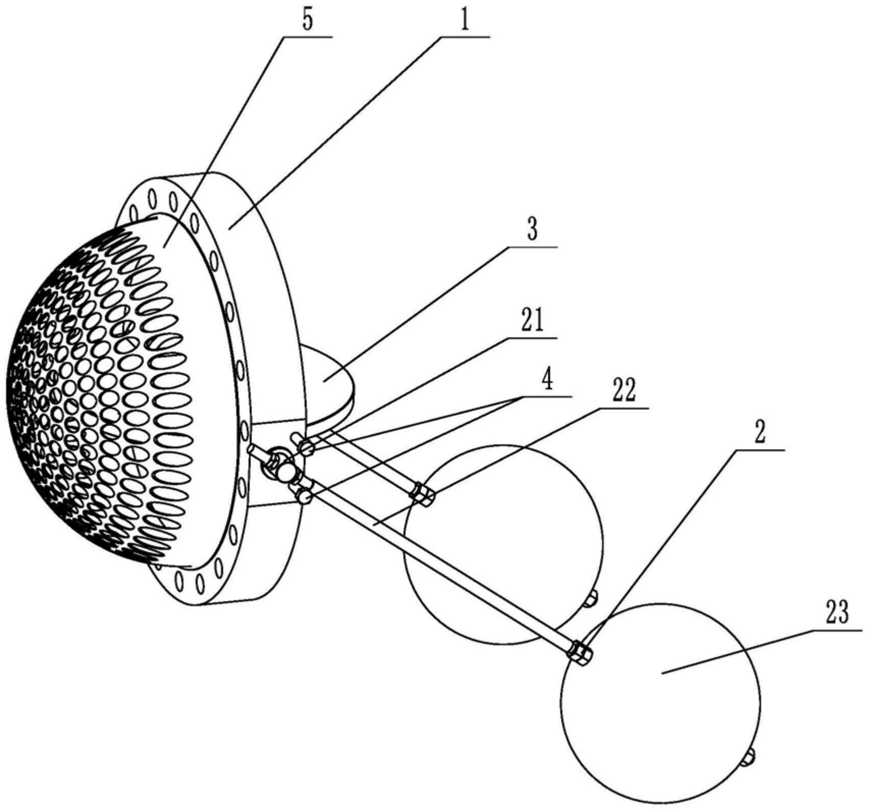
    1. A double-clip type float valve, comprising a valve body and a driving mechanism. The valve body is provided with a through medium channel in the axial direction. It is characterized in that the valve body is tubular and further comprises a butterfly plate that fits and seals with the inner wall of the medium channel. The driving mechanism comprises a valve shaft passing through the valve body and connected to the butterfly plate, a valve rod connected to the outer end of the valve shaft in the radial direction, and a float connected to the valve rod. The valve rod is provided with a limit bolt threadedly connected to the valve body in the swinging direction. The butterfly plate is rotatable relative to the valve body. The front end of the valve body located at the inlet of the medium channel is provided with a filter screen. The filter screen is hollow and hemispherical. The end surface of the valve body opposite the filter screen is provided with an annular groove. The open end of the filter screen is provided with a convex edge embedded in the annular groove.

    2. A wafer-type float valve according to claim 1, characterized in that the valve rod penetrates one end of the valve shaft located outside the valve body, and is threadedly engaged with the valve rod through a nut to clamp the valve shaft and achieve positioning of the valve rod.

    3. A wafer-type ball valve according to claim 2, characterized in that a step is provided at the position on the valve shaft connected to the valve body, a groove is provided at the position on the outer circumferential wall of the valve body corresponding to the step, and a gland is sleeved on the valve shaft, which is threadably connected to the groove and abuts against the step.

    4. A wafer-type ball valve according to claim 3, characterized in that a sealing groove is provided on the side of the groove facing the butterfly plate, and a sealing ring sleeved on the valve shaft is arranged in the sealing groove.

    5. A wafer-type ball valve according to claim 1, characterized in that an inner groove is provided on the side wall within the annular groove, and an elastic snap ring, which is used to press the convex edge and is compatible with the inner groove, is provided within the annular groove.

    6. A wafer-type ball valve according to claim 5, characterized in that the bottom of the convex edge is provided with a plurality of protrusions arranged around the center of the filter screen, and the annular groove is provided with a limiting groove adapted to the protrusions.

    7. A wafer-type float valve according to claim 6, characterized in that the protrusion is hemispherical. 8. A wafer-type float valve according to claim 7, characterized in that a clamping groove is provided at the junction of the protrusion and the protruding edge, and a clamping block adapted to the clamping groove is provided at the opening of the limiting groove.