Your location:

/ Valve products / check valve / API, JIS, DIN, GOST check valves / H61Y Forged Steel Y-Type Check Valve
全国销售热线:0577-67378222

Product classification of Kaiweixi

KAI WEI XI CHAN PIN FEN LEI
  • H61Y Forged Steel Y-Type Check Valve

  • More API, JIS, DIN, GOST check valves>>

  • More check valve>>

  • More valve>>

Contact Us
  • Phone:+86(577)6730 7899
  • Mobile:+86 189 6779 6135
  • Fax:+86(577)6738 7099
  • Email:Yannie@kaiweixi.com
  • Address:No. 1, Linxia Road, Sanqiao Industrial Zone, Oubei Street, Yongjia County, Zhejiang Province,china
  • Website:https://www.kaiweixi.com
Other valve products you may need
  • API Check Valve
  • H64Y Self-Sealing Power Plant Check Valve
  • DIN Swing Check Valve
  • DIN Lift Check Valve
  • DIN Ball Check Valve
H61Y Forged Steel Y-Type Check Valve

H61Y Forged Steel Y-Type Check Valve

  • Model:H61Y
  • Specification:DN10-50
  • Temperature:≤ 550 ℃
  • Medium:Water, Oil , Steam
  • Pressure:PN6-PN64
  • Connection method:NPT
  • Driving method:automated
  • Material:forged steel,forged stainless steel
x

Add QR code to serve you!

x

Add QR code to serve you!

x

Add QR code to serve you!

x
H61Y Forged Steel Y-Type Check ValveOverview

H61Y Forged Steel Y-Type Check Valve Overview

The H61Y Forged Steel Y-Type Check Valve is a specially designed check valve featuring a forged steel body with internal thread or butt-weld connections, characterized by a Y-shaped flow path and an internal lift-type disc structure. The valve body is forged from materials such as A105, offering excellent mechanical properties and pressure-bearing capacity. The sealing surfaces of the disc and seat typically employ metal hard seals overlay-welded with hard alloys.The valve operates by lifting the disc open under forward medium pressure and achieving rapid closure under the disc's own weight with spring assistance. The Y-shaped design ensures a smooth flow path transition, significantly reducing flow resistance and pressure loss.Specifically engineered for small-diameter pipelines with high pressure, high flow velocity, and stringent pressure drop requirements, this valve is widely used in petrochemical plants, power stations, high-pressure boiler feedwater systems, and instrument measurement pipelines. It serves as a high-performance, compact device for preventing medium backflow.

H61Y Forged Steel Y-Type Check Valve Product Image

H61Y Forged Steel Y-Type Check ValveCharacteristic

H61Y Forged Steel Y-Type Check Valve Features

1. Y-Type Flow Path with Low Pressure Loss Design  

  The unique Y-shaped valve body structure ensures smooth directional change of the medium flow, significantly reducing fluid resistance and pressure loss. This makes it particularly suitable for critical pipelines with high flow velocities or sensitivity to system pressure drops.

2. Forged Steel Body with High-Pressure Performance  

  The valve is integrally forged, providing dense and uniform material properties free from casting defects. Its exceptionally high mechanical strength ensures reliable operation under high pressure, high temperature, and frequent pressure fluctuations.

3. Wear-Resistant Hard Metal Sealing  

  The disc and seat feature hard alloy sealing surfaces, offering excellent resistance to erosion, high temperatures, and wear. This ensures long-lasting sealing reliability even under demanding operating conditions.

4. Rapid Closure and Compact Structure  

  Typically equipped with an auxiliary closing spring, the valve responds quickly and effectively prevents water hammer. Its compact design, with a shorter installation length compared to traditional right-angle check valves, saves valuable space.

5. Reliable Connections and Easy Maintenance  

  Available with internal thread or butt-weld connections for dependable sealing. The structural design facilitates online inspection or maintenance, and some models support quick replacement of internal sealing components.

H61Y Forged Steel Y-Type Check Valvestructure principle

H61Y Forged Steel Y-Type Check Valve Structure Diagram

Parts Name Material List

NO.NameMaterial
5gasket316 +graphte 316 + PTFE
4boltB7、B8、B16
3discStainless Steel, Carbon Steel
2bonnetStainless Steel, Carbon Steel
1bodyStainless Steel, Carbon Steel


H61Y Forged Steel Y-Type Check Valvetechnology parameter
性能规范表Performance Specification
公称压力Nominal Pressure2.0-15Mpa
强度试验压力Shell Test3-22.5
密封试验压力Seal Test2.2-16.5
适用温度Suitable Temp.≤550


H61Y Forged Steel Y-Type Check Valvestandard size

Dimensions Standard Requirements

1. The structural length of the valve shall conform to the standard GB/T 12221.

2. The connecting flange shall conform to the standard JB/T 3595.

H61Y Forged Steel Y-Type Check Valve View Drawing

H61Y Forged Steel Y-Type Check Valve Dimensions Table

口径SIZERB缩径LRB缩径HFB全径LFB全径H
DN1098859885
DN15988511095
DN2011095120105
DN25120105140114
DN32140114140114
DN40140114170132
DN50170132200145


Articles related to technology research and development
  • Slow-closing wafer check valve patent

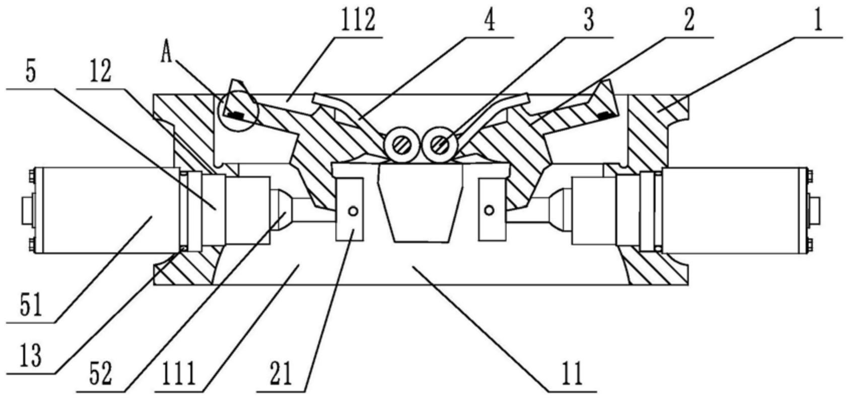
       The utility model provides a slow-closing wafer check valve, which includes a valve body, a valve disc, a valve shaft, and a torsion spring sleeved on the valve shaft. The valve body is provided with a medium channel for medium circulation in the axial direction, which includes an inlet end and an outlet end. The valve disc, valve shaft, and torsion spring are symmetrically arranged in two groups relative to the center of the valve body. The utility model further includes a damping device located at the inlet end, which includes a cylinder inserted on the valve body, a piston rod located inside the cylinder, a spring, and a cover connected to the outer end of the cylinder. The cylinder is provided with a first cavity and a second cavity that are connected and communicated. The cross-section of the second cavity is square, and its cross-sectional area is larger than that of the first cavity. One end of the piston rod located inside the medium channel is provided with a movable block. The utility model has low noise and technical characteristics of quick opening, slow closing, and water hammer elimination, enabling light-load pump start-up and preventing the generation of water hammer during pump shutdown.
    1. A slow-closing wafer check valve, comprising a valve body, a valve disc, a valve shaft, and a torsion spring sleeved on the valve shaft. The valve body is provided with a medium passage for medium circulation in the axial direction, and the medium passage includes an inlet end and an outlet end. The valve disc, valve shaft, and torsion spring are symmetrically arranged in two groups relative to the center of the valve body. The valve also comprises a damping device located at the inlet end. The damping device includes a cylinder inserted on the valve body, a piston rod located inside the cylinder, a spring, and a cover connected to the outer end of the cylinder. The cylinder is provided with a first cavity and a second cavity that are connected and communicated. The cross-section of the second cavity is square, and the cross-sectional area of the second cavity is larger than that of the first cavity. One end of the piston rod is located inside the second cavity, and the other end penetrates through the first cavity and is located inside the medium passage. The end of the piston rod located inside the medium passage is provided with a movable block, and the end of the piston rod located inside the second cavity is provided with an external thread. The second cavity is provided with a limit plate that is adapted to and threadedly connected with the piston rod. The spring is sleeved on the piston rod, with one end abutting against the limit plate and the other end abutting against the inner wall of the second cavity. The side of the valve disc facing the piston rod is provided with a driving block that cooperates with the movable block. During the closing process of the valve disc, the side of the driving block facing the center of the valve body cooperates with the movable block to achieve displacement of the piston rod relative to the cylinder towards the center of the valve body. The damping device is symmetrically arranged in two groups relative to the center of the valve body.

    2. A slow-closing wafer check valve according to claim 1, characterized in that a square hole is axially provided at the end of the piston rod located in the second cavity, an adjuster is inserted at a position on the cover corresponding to the square hole, a driving rod adapted to the square hole is provided at the end of the adjuster, and the adjuster is rotatable relative to the cover.

    3. A slow-closing wafer check valve according to claim 2, characterized in that a limit slot is provided at the connection between the cover and the regulator, and a limit mechanism is arranged inside the limit slot. The limit mechanism comprises a ball, a tower spring connected to the ball, and a positioning column for fixing the tower spring. At least four engaging slots adapted to the ball are provided circumferentially at the connection between the regulator and the cover.

    4. A slow-closing wafer check valve according to claim 3, characterized in that the top edge of the engaging groove is provided with a rounded corner.

    5. A slow-closing wafer check valve according to claim 1, characterized in that the valve body is provided with a stepped groove adapted to the cylinder body.

    6. A slow-closing wafer check valve according to claim 5, characterized in that a sealing ring is sleeved at the connection between the cylinder and the valve body.

    7. A slow-closing wafer check valve according to claim 1, characterized in that the valve disc is provided with a build-up welding layer that is sealed with the valve body. 8. A slow-closing wafer check valve according to claim 7, characterized in that one side of the build-up welding layer is provided with vulcanized rubber that is sealed with the valve body.