Your location:

/ Valve products / check valve / API, JIS, DIN, GOST check valves / JIS Standard Stop-Check Valve
全国销售热线:0577-67378222

Product classification of Kaiweixi

KAI WEI XI CHAN PIN FEN LEI
  • JIS Standard Stop-Check Valve

  • More API, JIS, DIN, GOST check valves>>

  • More check valve>>

  • More valve>>

Contact Us
  • Phone:+86(577)6730 7899
  • Mobile:+86 189 6779 6135
  • Fax:+86(577)6738 7099
  • Email:Yannie@kaiweixi.com
  • Address:No. 1, Linxia Road, Sanqiao Industrial Zone, Oubei Street, Yongjia County, Zhejiang Province,china
  • Website:https://www.kaiweixi.com
Other valve products you may need
  • API Check Valve
  • H64Y Self-Sealing Power Plant Check Valve
  • H61Y Forged Steel Y-Type Check Valve
  • DIN Swing Check Valve
  • DIN Lift Check Valve
JIS Standard Stop-Check Valve

JIS Standard Stop-Check Valve

  • Model:J41H-5K/J41H-10K/J41H-20K/J41Y-5K/J41Y-10K/J41Y-20K
  • Specification:1/2”- 16”
  • Temperature:≤550℃
  • Medium:Water, steam, oil and similar liquids, gases
  • Pressure:5K/10K/20K
  • Connection method:flange
  • Driving method:Handwheel
  • Material:Cast steel, stainless steel
x

Add QR code to serve you!

x

Add QR code to serve you!

x

Add QR code to serve you!

x
JIS Standard Stop-Check ValveOverview

Overview

The JIS standard stop valve is a pipeline shut-off valve strictly designed and manufactured according to Japanese Industrial Standards (JIS). It utilizes a stem to drive the disc in a vertical lifting motion along the centerline of the seat, enabling the opening, closing, and flow regulation of the medium within the pipeline. Its design and manufacturing strictly adhere to standards such as JIS B2002 (face-to-face dimensions), JIS B2210 (flange dimensions), and JIS B2071/2081 (cast iron/cast steel stop valves), ensuring precise matching and interchangeability with JIS standard piping systems. Structurally, the valve body and bonnet employ a flanged bolted connection or a pressure self-sealing design. The sealing surfaces of the disc and seat are overlaid with hard alloy and precision ground, forming a wear-resistant and corrosion-resistant metal sealing pair. This, combined with a precision-machined stem and high-quality packing, creates a reliable sealing system that effectively prevents internal and external media leakage. The valve can be equipped with manual, electric, or pneumatic actuators as required. It is widely used in process piping systems within the petroleum, chemical, light industry sectors, and in joint ventures involving Japanese partners. It is particularly suitable for the isolation and control of non-corrosive or mildly corrosive media such as water, steam, and oil, serving as a critical control component ensuring the safe and reliable operation of JIS standard piping systems.

JIS Standard Stop-Check Valve Product Image

JIS Standard Stop-Check ValveCharacteristic

Features

1、Strict Compliance with JIS Standard System: Strictly designed and manufactured according to Japanese Industrial Standards such as JIS B2002, JIS B2210, and JIS B2071/2081. The face-to-face dimensions, flange connection sizes, and pressure-temperature ratings are fully compatible with JIS standard piping systems, ensuring precise interchangeability and reliable connection with JIS standard pipes and equipment.

2、Excellent Sealing Performance: The sealing surfaces of the disc and seat are overlaid with cobalt-based hard alloy or Stellite. Through precision grinding, they form a high-hardness, wear-resistant metal sealing pair that effectively resists media erosion, achieving positive shut-off and meeting zero-leakage requirements.

3、Adaptability to Harsh Conditions: Key pressure-containing parts are manufactured from high-quality stainless steel or heat-resistant alloy steel, offering excellent high-temperature strength and corrosion resistance. The sealing surfaces undergo special hardening treatment, ensuring long-term stable operation under high temperature, high pressure, and in harsh media containing trace particles.

4、Reliable Stem Sealing: The contact area between the stem and packing is precision-polished. Combined with flexible graphite or formed PTFE packing, evenly compressed by the packing gland, it forms a reliable dynamic sealing structure that effectively prevents external media leakage and enhances system safety.

5、Smooth and Flexible Operation: The top of the disc is connected to the stem via a T-slot and features a precise guiding structure, ensuring smooth operation without binding during opening and closing. It can be configured with a handwheel, bevel gear, electric, or pneumatic actuator, offering low operating torque and clearly discernible open/close positions.

6、Compact Structure, Convenient Maintenance: The compact structural design results in light overall weight and requires minimal installation space. The bonnet utilizes a flanged bolted connection or a pressure self-sealing structure, facilitating internal valve inspection and easy replacement of sealing components, thereby reducing maintenance costs.

7、Broad Applicability: Suitable for various non-corrosive or mildly corrosive media such as water, steam, oil, and gas. Widely used in process piping systems within the petroleum, chemical, light industry, textile sectors, and joint ventures involving Japanese partners. It is a key shut-off and control component in JIS standard piping systems.

JIS Standard Stop-Check Valvestructure principle

JIS Standard Stop-Check Valve Structure Diagram

零部件名称材料表Part Name and Material List

阀盖 阀瓣A216 WCBA352 LCBA217 WC6A217 WC9A217 C5A351 CF8A351 CF8MA351 CF3A351 CF3M
阀杆A182 F6A182 F304A182 F316A182 F304LA182 F316L


JIS Standard Stop-Check Valvetechnology parameter

Performance Specification Table

性能规范表Performance Specification Table
公称压力Nominal Pressure10K/20KMPa
适用温度Applicable Temperature≤550


JIS Standard Stop-Check Valvestandard size

JIS Standard Stop-Check Valve Dimensional Drawing

JIS Standard Stop-Check Valve Dimensional Table

10K规格Size(mm) 尺寸Dimensions(mm)
inchDNLDD1D2bz-ΦdHD0
1/2”15108957052124-Φ15200100
3/4"201171007558144-Φ15205120
1"251271259070144-Φ19230140
11/4”3214013510080164-Φ19240140
11/2”4016514010585164-Φ19270160
2"50203155120100164-Φ19300200
21/2”65216175140120184-Φ19340220
3”80241185150130188-Φ19360240
4”100292210175155188-Φ19420280
5”125356250210185208-Φ23460350
6”150406280240215228-Φ23500400
8"2004953302902652212-Φ23590450
10"2506224003553252412-Φ25710500
12"3006984454003702416-Φ25810550
14”3507874904454152616-Φ25880600
16”4009145605104752816-Φ27940650
20KinchDNLDD1D2bz-Φ dHD0
1/2"15152957052144-Φ 15220120
3/4"201781007558164-Φ 15230120
1"252031259070164-Φ 19260140
11/4”3221613510080184-Φ 19280140
11/2”4022914010585184-Φ 19300200
2”50267155120100228-Φ 19330240
21/2”65292175140120248-Φ 19360240
3”80318200160135268-Φ 23400280
4”100356225185160288-Φ 23450320
5”125400270225195308-Φ 25500400
6”1504443052602303212-Φ 25540450
8”2005593503052753412-Φ 25670500
10"2506224303803453812-Φ 27770550
12"3007114804303954016-Φ 27855600
14”3507625404804404416-Φ 33920650
16”4008646055404954616-Φ 33970700


Articles related to technology research and development
  • Slow-closing wafer check valve patent

       The utility model provides a slow-closing wafer check valve, which includes a valve body, a valve disc, a valve shaft, and a torsion spring sleeved on the valve shaft. The valve body is provided with a medium channel for medium circulation in the axial direction, which includes an inlet end and an outlet end. The valve disc, valve shaft, and torsion spring are symmetrically arranged in two groups relative to the center of the valve body. The utility model further includes a damping device located at the inlet end, which includes a cylinder inserted on the valve body, a piston rod located inside the cylinder, a spring, and a cover connected to the outer end of the cylinder. The cylinder is provided with a first cavity and a second cavity that are connected and communicated. The cross-section of the second cavity is square, and its cross-sectional area is larger than that of the first cavity. One end of the piston rod located inside the medium channel is provided with a movable block. The utility model has low noise and technical characteristics of quick opening, slow closing, and water hammer elimination, enabling light-load pump start-up and preventing the generation of water hammer during pump shutdown.
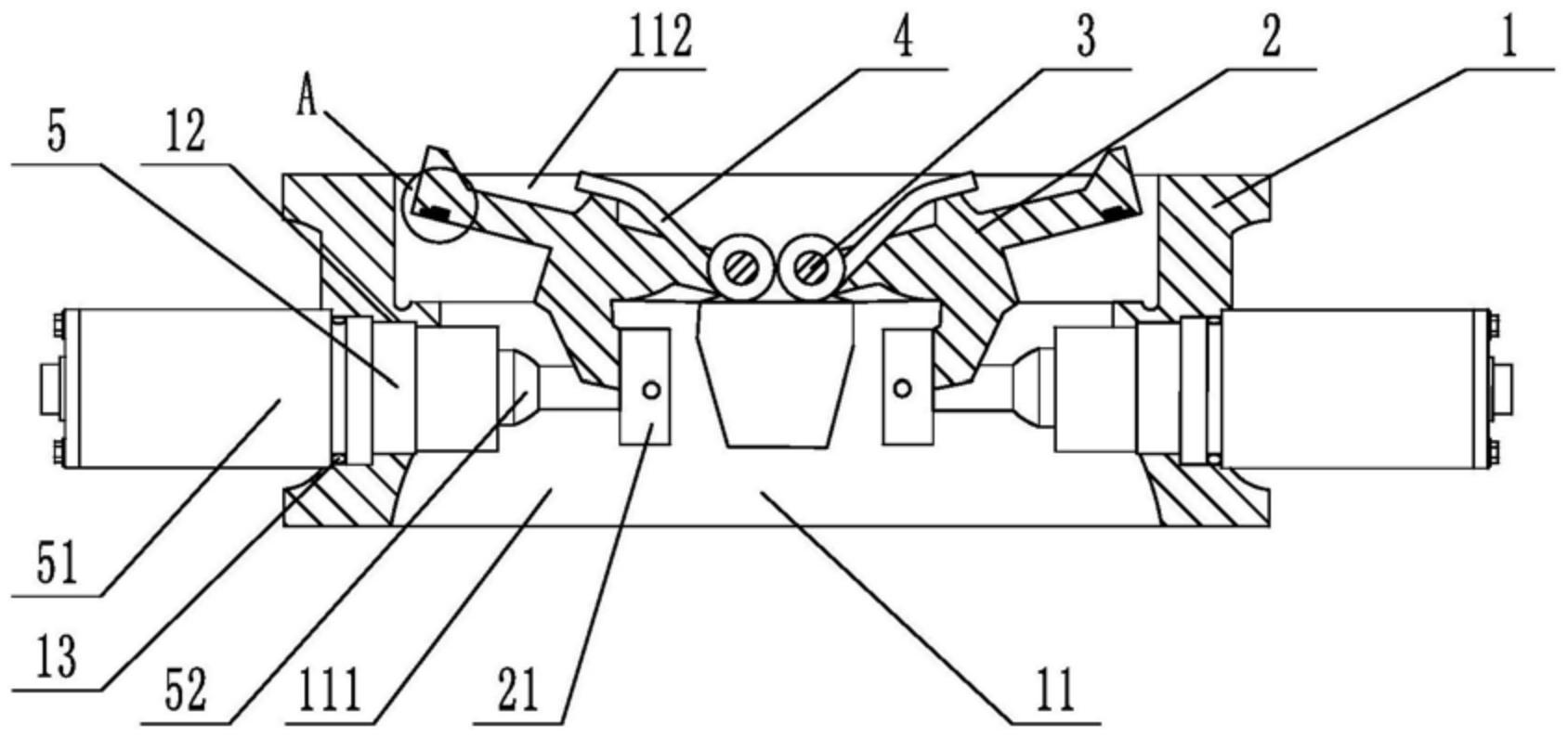
    1. A slow-closing wafer check valve, comprising a valve body, a valve disc, a valve shaft, and a torsion spring sleeved on the valve shaft. The valve body is provided with a medium passage for medium circulation in the axial direction, and the medium passage includes an inlet end and an outlet end. The valve disc, valve shaft, and torsion spring are symmetrically arranged in two groups relative to the center of the valve body. The valve also comprises a damping device located at the inlet end. The damping device includes a cylinder inserted on the valve body, a piston rod located inside the cylinder, a spring, and a cover connected to the outer end of the cylinder. The cylinder is provided with a first cavity and a second cavity that are connected and communicated. The cross-section of the second cavity is square, and the cross-sectional area of the second cavity is larger than that of the first cavity. One end of the piston rod is located inside the second cavity, and the other end penetrates through the first cavity and is located inside the medium passage. The end of the piston rod located inside the medium passage is provided with a movable block, and the end of the piston rod located inside the second cavity is provided with an external thread. The second cavity is provided with a limit plate that is adapted to and threadedly connected with the piston rod. The spring is sleeved on the piston rod, with one end abutting against the limit plate and the other end abutting against the inner wall of the second cavity. The side of the valve disc facing the piston rod is provided with a driving block that cooperates with the movable block. During the closing process of the valve disc, the side of the driving block facing the center of the valve body cooperates with the movable block to achieve displacement of the piston rod relative to the cylinder towards the center of the valve body. The damping device is symmetrically arranged in two groups relative to the center of the valve body.

    2. A slow-closing wafer check valve according to claim 1, characterized in that a square hole is axially provided at the end of the piston rod located in the second cavity, an adjuster is inserted at a position on the cover corresponding to the square hole, a driving rod adapted to the square hole is provided at the end of the adjuster, and the adjuster is rotatable relative to the cover.

    3. A slow-closing wafer check valve according to claim 2, characterized in that a limit slot is provided at the connection between the cover and the regulator, and a limit mechanism is arranged inside the limit slot. The limit mechanism comprises a ball, a tower spring connected to the ball, and a positioning column for fixing the tower spring. At least four engaging slots adapted to the ball are provided circumferentially at the connection between the regulator and the cover.

    4. A slow-closing wafer check valve according to claim 3, characterized in that the top edge of the engaging groove is provided with a rounded corner.

    5. A slow-closing wafer check valve according to claim 1, characterized in that the valve body is provided with a stepped groove adapted to the cylinder body.

    6. A slow-closing wafer check valve according to claim 5, characterized in that a sealing ring is sleeved at the connection between the cylinder and the valve body.

    7. A slow-closing wafer check valve according to claim 1, characterized in that the valve disc is provided with a build-up welding layer that is sealed with the valve body. 8. A slow-closing wafer check valve according to claim 7, characterized in that one side of the build-up welding layer is provided with vulcanized rubber that is sealed with the valve body.