Your location:

/ Valve products / control valve / Pneumatic Control Valve / PZ673 Pneumatic Wafer Knife Gate Valve
全国销售热线:0577-67378222

Product classification of Kaiweixi

KAI WEI XI CHAN PIN FEN LEI
  • PZ673 Pneumatic Wafer Knife Gate Valve

  • More Pneumatic Control Valve>>

  • More control valve>>

  • More valve>>

Contact Us
  • Phone:+86(577)6730 7899
  • Mobile:+86 195 1816 9569
  • Fax:+86(577)6738 7099
  • Email:Lucas@kaiweixi.com
  • Address:No. 1, Linxia Road, Oubei Street, Yongjia County, Wenzhou City, Zhejiang Province,china
  • Website:https://www.kaiweixi.com
Other valve products you may need
  • ZJHP Compact Pneumatic Diaphragm Single-seated Regulating Valve
  • ZJHM Compact Pneumatic Diaphragm Cage-Guided Control Valve
  • ZJHS Compact Pneumatic Diaphragm Angle Single-seated Control Valve
  • ZZJ Pneumatic Slurry Valve
  • Pneumatic Diaphragm Double-seated Straight-through Control Valve
PZ673 Pneumatic Wafer Knife Gate Valve

PZ673 Pneumatic Wafer Knife Gate Valve

  • Model:PZ673H-10C/PZ673H-16C/PZ673X-6C/PZ673X-10C/PZ673F-6C/PZ673F-10C/PZ673F-16C/PZ673H-10P/PZ673H-16P/PZ673X-6P/PZ673X-10P/PZ673F-6P/PZ673F-10P/PZ673F-16P
  • Specification:DN50~1200
  • Temperature:-40-450℃
  • Medium:Slurry, pulp, sewage, and applications requiring rapid shut-off
  • Pressure:PN0.6~1.6MPa
  • Connection method:Wafer
  • Driving method:Pneumatic
  • Material:Carbon steel, stainless steel
x

Add QR code to serve you!

x

Add QR code to serve you!

x

Add QR code to serve you!

x
PZ673 Pneumatic Wafer Knife Gate ValveOverview

PZ673 Pneumatic Wafer Knife Gate Valve is an industrial automation execution unit combining a pneumatic actuator with an ultra-thin knife gate valve body. Utilizing compressed air as the power source, the pneumatic cylinder drives the piston to move the gate plate in a linear reciprocating motion, thereby opening or closing the pipeline. The core design features a gate plate with a sharp knife-edge at the bottom, which effectively shears through fibers, paper pulp, wood pulp, and impurities at the moment of closing to prevent jamming. The letters H, X, and F represent metal hard seal, rubber soft seal, and fluoroplastic seal, respectively, to meet various temperature, pressure, and corrosive conditions. Known for its short face-to-face dimension, light weight, and low flow resistance, this valve is widely used in paper making, mining, coal washing, chemicals, and sewage treatment systems.

Product Image of PZ673 Pneumatic Wafer Knife Gate Valve

PZ673 Pneumatic Wafer Knife Gate ValveCharacteristic

1. Ultra-short structure saves space:The wafer-style thin design ensures overall dimensions and weight are significantly lower than traditional gate valves. This saves installation space and reduces mechanical loads on the pipeline system, lowering support costs.
2.Knife-edge gate for powerful shearing:The bottom of the gate is precision-machined into a wedge-shaped edge. It provides a strong shearing effect during closing, easily cutting through impurities and fibers in viscous media to eliminate the risk of sticking or incomplete closure.
3.Full-bore design and low resistance:When fully open, the flow area matches the pipe diameter exactly, resulting in an extremely low resistance coefficient. This structure prevents media deposition and significantly reduces pumping energy consumption.
4.Powerful and stable pneumatic drive:Equipped with high-performance pneumatic cylinders, providing large output thrust and rapid response. It can be configured with solenoid valves and limit switches for remote control and supports fail-safe pre-setting.
5.Diverse sealing configurations:Available in H (metal seat for heat/wear resistance), X (rubber for tight seal), and F (PTFE for anti-corrosion) materials. The scientific seat design ensures reliable performance in both pressure directions.
6.Durable internal materials:Body and internals are available in cast steel, stainless steel, or wear-resistant alloys. The gate surface is typically hard-chrome plated or nitrided to enhance hardness and erosion resistance for long-term stability.
7.Modular design for easy service:The simple structure features minimal wearing parts. Actuator-to-body connections are standardized, allowing for online inspection and replacement of packing and seals without removing the valve from the line.
8.Intrinsic safety and protection:Driven by compressed air, it eliminates spark risks, providing natural safety for hazardous zones such as powder-dense, flammable, or explosive industrial environments.

PZ673 Pneumatic Wafer Knife Gate Valvestructure principle

Structural Drawing of  PZ673 Pneumatic Wafer Knife Gate Valve

List of Component Names and Materials

Part NameMaterial NameMaterial Grade/Mark
Round NutHigh-quality Carbon Steel25
HandwheelGrey Cast IronHT200
Bearing GlandHigh-quality Carbon Steel35
Stem NutAluminum Bronze / Aluminum BrassZCuAl9Mn2... / ZCuZn25Al6Fe3Mn3
Bearing51110
StemStainless Steel304, 316, 2Cr13
Yoke / BracketCarbon Steel, Stainless SteelWCB, CF8, etc.
Wedge / DiscStainless Steel304, 316, 304L, 316L, 2Cr13
Bolt and NutHigh-quality Carbon Steel35
Packing GlandCarbon SteelWCB
PackingFlexible Graphite, PTFE Fiber, etc.
Valve BodyCarbon Steel, Stainless SteelWCB, CF8, CF3, CF8M, CF3M, etc.


PZ673 Pneumatic Wafer Knife Gate Valvetechnology parameter

Performance Specification Sheet

Performance Specification Sheet
Nominal Pressure0.61.01.6MPa
Strength test pressure0.91.52.4
Sealing test pressure0.661.11.76
Applicable Temperature-40-450


PZ673 Pneumatic Wafer Knife Gate Valvestandard size

Standard requirements for external dimensions

1.Design & Manufacture: JB/T869l-1998 MSS SP-81

2.Flange Dimensions:GB/T9113.1-2000

3.Face-to-Face Dimensions:GB/T1-5188.2-94

Outline Drawing of PZ673 Pneumatic Wafer Knife Gate Valve

Outline dimension table(Unit:mm)

MPaDNLDD1D2HN-MA
1.050431601251003304-M16180
65461801451203604-M16180
80461951601353904-M16220
100522151801554408-M16220
125562452101855108-M16230
150562802402106008-M20280
200603352952857008-M20360
2506839035032084012-M20360
3007844040036898012-M20400
35078500460428111016-M20400
400102565515482125016-M22400
450114615565532138020-M22530
500127670620585153020-M22530
600154780725685180020-M27600
700165895840800215024-M27600
8001901010950898242024-M30680
900203111010501005268028-M30680
1000218122011601115310028-M30700
1200254145013801325345032-M36800
1.65043160125993304-M16180
65461851451203604-M16180
80462001601353908-M16220
100522201801554408-M16220
125552502101855108-M16230
150562852402106008-M20280
2006034029526570012-M20360
2506840535531084012-M22360
3007846041037596012-M22400
35078520470435111016-M22400
400102580525485125016-M27400
450114640585545138020-M27530
500127715650600153020-M30530
600154840770720180020-M36600
700165910840788215024-M36600
8001901025950898242024-M36680
90020311251050998268028-M38680
1000216125511701110310028-M42700
12002541485139013253450


Articles related to technology research and development
  • Dynamic balance electric control valve Patent

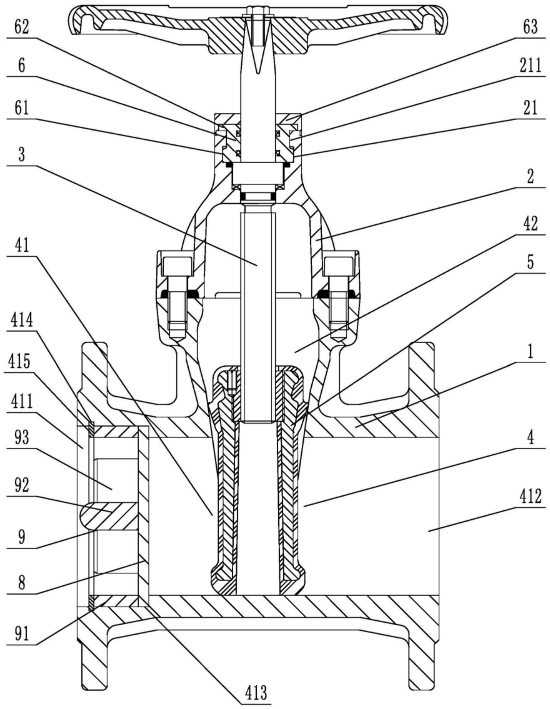
       The utility model provides a dynamically balanced electric regulating valve, which includes a valve body, a valve cover, a valve rod, a valve core installed inside the valve body and connected to the valve rod, and an actuator installed on the valve cover and connected to the top end of the valve rod. The valve body is internally provided with a water inlet chamber, a valve cavity, and a water outlet chamber in order towards the direction of medium flow. The valve core is in the shape of a bucket with its opening facing downwards. The valve core is located inside the valve cavity and is used for connecting or cutting off between the water inlet chamber and the valve cavity. The top of the valve core is provided with a through port for medium circulation. Above the through port, there is a filter cover detachably connected to the valve core. The valve rod is provided with a step, and the outside of the step is covered with an elastic sleeve that fits it. The top of the filter cover is provided with a fixing hole that fits the elastic sleeve. This utility model can filter the medium, is simple to install, time-saving, labor-saving, and can reduce the medium pressure inside the valve body, extending the service life of the valve core.

    1. A dynamic balance electric regulating valve, comprising a valve body, a valve cover, a valve rod, a valve core installed inside the valve body and connected to the valve rod, and an actuator installed on the valve cover and connected to the top end of the valve rod. Its characteristic lies in that the valve body is sequentially provided with an inlet chamber, a valve cavity, and an outlet chamber in the direction of medium flow. The valve core is in the shape of a bucket with an opening facing downwards. The valve core is located inside the valve cavity and is used for connecting or cutting off between the inlet chamber and the valve cavity. The top of the valve core is provided with a port for medium circulation. Above the port, there is a filter cover detachably connected to the valve core. The valve rod is provided with a step, and the outside of the step is covered with an elastic sleeve that fits it. The top of the filter cover is provided with a fixing hole that fits the elastic sleeve.

    2. A dynamic balance electric regulating valve according to claim 1, characterized in that the bottom of the valve body is provided with a downward-opening groove, which is connected to the valve cavity through a through hole. A bottom cover connected to the valve body is arranged below the groove, and a pressure relief mechanism is arranged inside the groove. The pressure relief mechanism comprises a force-receiving member, a pressure plate connected to the force-receiving member, and a first spring arranged below the pressure plate and abutting against the bottom cover. The force-receiving member comprises a flow diversion block protruding from the through hole and a connecting rod connected to the flow diversion block, and the connecting rod passes through the pressure plate and is locked and fixed by a nut.

    3. A dynamic balance electric regulating valve according to claim 2, characterized in that the top end of the pressure plate is pressed against the top wall of the groove, the bottom of the pressure plate is provided with a boss, and the top end of the first spring is sleeved on the boss.

    4. A dynamic balance electric control valve according to claim 1, characterized in that the valve rod is arranged through the valve cover, a sealing cover threadedly connected to the valve cover is sleeved on the valve rod, a convex ring abutting against the valve cover is arranged on the outer circumferential wall of the sealing cover, a nut cover threadedly connected to the sealing cover is arranged at the connection between the sealing cover and the valve rod, an installation groove is arranged at the connection between the nut cover and the valve rod, a plurality of O-rings adapted to the valve rod are stacked in the installation groove, and a packing gland threadedly connected to the installation groove is arranged above the O-rings.

    5. A dynamic balance electric control valve according to claim 4, characterized in that a second spring is arranged between the packing gland and the O-ring.

    6. A dynamic balance electric control valve according to claim 5, characterized in that a sealing ring adapted to the valve rod is arranged inside the nut cover below the installation groove.

    7. A dynamic balance electric control valve according to claim 6, characterized in that the bottom of the sealing cover is provided with a thrust ring that is threadedly connected to the sealing cover and abuts against the bottom end of the valve cover.

    8. A dynamic balance electric regulating valve according to claim 1, characterized in that the top surface of the elastic sleeve is higher than the top surface of the filter cover.

    9. A dynamic balance electric control valve according to claim 8, characterized in that the filter cover is connected to the valve core through threads.