Your location:

/ Valve products / control valve / Electric Control Valve / MDFH Pulse Jet Solenoid Valve for Dust Collector
全国销售热线:0577-67378222

Product classification of Kaiweixi

KAI WEI XI CHAN PIN FEN LEI
  • MDFH Pulse Jet Solenoid Valve for Dust Collector

  • More Electric Control Valve>>

  • More control valve>>

  • More valve>>

Contact Us
  • Phone:+86(577)6730 7899
  • Mobile:+86 195 1816 9569
  • Fax:+86(577)6738 7099
  • Email:Lucas@kaiweixi.com
  • Address:No. 1, Linxia Road, Oubei Street, Yongjia County, Wenzhou City, Zhejiang Province,china
  • Website:https://www.kaiweixi.com
Other valve products you may need
  • BY42 Electric Louver Butterfly Valve
  • ZDG High-Performance Shut-off Butterfly Valve
  • ZDLP Electronic Electric Straight-through Single-seated Control Valve
  • ZQ High-Performance Electric Metal-Sealed Ball Valve
  • UPVC Electric Modulating Ball Valve
MDFH Pulse Jet Solenoid Valve for Dust Collector

MDFH Pulse Jet Solenoid Valve for Dust Collector

  • Model:MDFH
  • Specification:DN20~65
  • Temperature:≤80℃
  • Medium::Accepts pulse signals; used for on/off control of compressed air in pulse jet dust collection systems
  • Pressure:≤1.0 MPa
  • Connection method:Threaded
  • Driving method:Electric
  • Material:Aluminum alloy, stainless steel
x

Add QR code to serve you!

x

Add QR code to serve you!

x

Add QR code to serve you!

x
MDFH Pulse Jet Solenoid Valve for Dust CollectorOverview

The MDFH series pulse jet solenoid valve is the key execution mechanism in the cleaning and jetting system of baghouse dust collectors. Specifically designed to receive electrical signal commands from a pulse controller, the valve opens the air circuit instantaneously via an electromagnetic pilot mechanism. It injects compressed air from the storage tank into the filter bags in pulse form, causing rapid expansion and vibration of the bags to shake off accumulated dust. The MDFH series features a specialized streamlined internal cavity design, enabling the release of a massive instantaneous airflow within milliseconds. With a premium aluminum alloy body and high-performance reinforced diaphragms, this valve offers rapid response, high jet volume, low flow resistance, and an extended service life, serving as the core component for automated and efficient industrial dust collection.
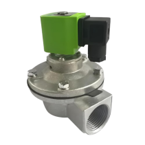
Product Image of MDFH Pulse Jet Solenoid Valve for Dust Collector

MDFH Pulse Jet Solenoid Valve for Dust CollectorCharacteristic

1.Rapid response and powerful jetting:Utilizes a pilot-operated diaphragm structure with a response time of only tens of milliseconds. The instantaneous high-impact airflow provides superior cleaning results, effectively maintaining the permeability of filter bags.
2.High-strength and lightweight body:The body is made of premium die-cast aluminum alloy, ensuring low weight and structural stability. The surface is precision-machined and treated with anti-corrosion coating to withstand dusty and humid industrial environments.
3.High-performance long-life diaphragm:The core seal uses a specialized reinforced rubber diaphragm with excellent fatigue strength, wear resistance, and flexibility, ensuring over a million cycles without failure.
4.Low flow resistance and high capacity:The internal flow path is aerodynamically optimized with a large bore and smooth walls. This minimizes pressure loss within the valve and maximizes the kinetic energy of the jet.
5.Low power and high insulation coil:The electromagnetic coil features an optimized circuit design with low temperature rise and high starting torque. Built-in quality seals provide excellent insulation for high-frequency pulse duty.
6.Versatile connection options:Available with internal threads, external threads, or flanged interfaces. The compact structure allows for dense arrangement on air headers, saving installation space.
7.Reliable sealing integrity:Precision-machined pilot holes and primary sealing surfaces ensure zero leakage in the closed position, preventing energy loss in the compressed air system.
8.Easy modular maintenance:The simple structure of the actuator and valve body allows for online inspection and replacement of diaphragms or springs by removing the cover bolts without dismantling the piping, reducing O&M costs.

MDFH Pulse Jet Solenoid Valve for Dust Collectorstructure principle

Structural Drawing of MDFH Pulse Jet Solenoid Valve for Dust Collector

List of Component Names and Materials

ComponentMaterial
Valve BodyADC 12 Die-cast Aluminum
Diaphragm and SealsHigh-quality NBR (Nitrile Rubber)
Spring321 Stainless Steel
Screws and Ferrules304 Stainless Steel
Armature430FR Stainless Steel
Solenoid CoilThermoset with high-quality copper coil


MDFH Pulse Jet Solenoid Valve for Dust Collectortechnology parameter

Performance Specification Sheet

Performance Specification Sheet
Nominal Pressure1.0MPa
Strength test pressure1.5
Sealing test pressure1.1
Applicable Temperature0~80

Standard requirements for external dimensions

1. The structural length of the valve shall comply with the standard of GB/T12221

2. Connecting flanges according to GB/T17241.6 standard


MDFH Pulse Jet Solenoid Valve for Dust Collectorstandard size

Outline dimension table(Unit:mm)

Dia. (mm)Dia. (inch)Main Diaphragm (mm)External Conn. (mm)Blowpipe IDWeight (kg)KV/CV
Ø203/4"8027200.6517.55/20.48
Ø251"9634250.826.16/30.53
Ø401 1/2"11148401.445.85/53.47
Ø502"160Ø60502.461.24/71.47
Ø622 1/2"188Ø75623.5129.26/150.85
Ø763"200Ø89764.3159.95/186.66
Ø893 1/2"227Ø102895.9202/230
Ø1023 1/2"255Ø1141027.3260/303
Ø203/4"8027200.917.55/20.48
Ø251"9634251.326.16/30.53
Ø401 1/2"1114840245.85/53.47
Ø203/4"8027201.3517.55/20.48
Ø251"9634251.6526.16/30.53
Ø401 1/2"11148402.545.85/53.47


Articles related to technology research and development
  • Dynamic balance electric control valve Patent

       The utility model provides a dynamically balanced electric regulating valve, which includes a valve body, a valve cover, a valve rod, a valve core installed inside the valve body and connected to the valve rod, and an actuator installed on the valve cover and connected to the top end of the valve rod. The valve body is internally provided with a water inlet chamber, a valve cavity, and a water outlet chamber in order towards the direction of medium flow. The valve core is in the shape of a bucket with its opening facing downwards. The valve core is located inside the valve cavity and is used for connecting or cutting off between the water inlet chamber and the valve cavity. The top of the valve core is provided with a through port for medium circulation. Above the through port, there is a filter cover detachably connected to the valve core. The valve rod is provided with a step, and the outside of the step is covered with an elastic sleeve that fits it. The top of the filter cover is provided with a fixing hole that fits the elastic sleeve. This utility model can filter the medium, is simple to install, time-saving, labor-saving, and can reduce the medium pressure inside the valve body, extending the service life of the valve core.

    1. A dynamic balance electric regulating valve, comprising a valve body, a valve cover, a valve rod, a valve core installed inside the valve body and connected to the valve rod, and an actuator installed on the valve cover and connected to the top end of the valve rod. Its characteristic lies in that the valve body is sequentially provided with an inlet chamber, a valve cavity, and an outlet chamber in the direction of medium flow. The valve core is in the shape of a bucket with an opening facing downwards. The valve core is located inside the valve cavity and is used for connecting or cutting off between the inlet chamber and the valve cavity. The top of the valve core is provided with a port for medium circulation. Above the port, there is a filter cover detachably connected to the valve core. The valve rod is provided with a step, and the outside of the step is covered with an elastic sleeve that fits it. The top of the filter cover is provided with a fixing hole that fits the elastic sleeve.

    2. A dynamic balance electric regulating valve according to claim 1, characterized in that the bottom of the valve body is provided with a downward-opening groove, which is connected to the valve cavity through a through hole. A bottom cover connected to the valve body is arranged below the groove, and a pressure relief mechanism is arranged inside the groove. The pressure relief mechanism comprises a force-receiving member, a pressure plate connected to the force-receiving member, and a first spring arranged below the pressure plate and abutting against the bottom cover. The force-receiving member comprises a flow diversion block protruding from the through hole and a connecting rod connected to the flow diversion block, and the connecting rod passes through the pressure plate and is locked and fixed by a nut.

    3. A dynamic balance electric regulating valve according to claim 2, characterized in that the top end of the pressure plate is pressed against the top wall of the groove, the bottom of the pressure plate is provided with a boss, and the top end of the first spring is sleeved on the boss.

    4. A dynamic balance electric control valve according to claim 1, characterized in that the valve rod is arranged through the valve cover, a sealing cover threadedly connected to the valve cover is sleeved on the valve rod, a convex ring abutting against the valve cover is arranged on the outer circumferential wall of the sealing cover, a nut cover threadedly connected to the sealing cover is arranged at the connection between the sealing cover and the valve rod, an installation groove is arranged at the connection between the nut cover and the valve rod, a plurality of O-rings adapted to the valve rod are stacked in the installation groove, and a packing gland threadedly connected to the installation groove is arranged above the O-rings.

    5. A dynamic balance electric control valve according to claim 4, characterized in that a second spring is arranged between the packing gland and the O-ring.

    6. A dynamic balance electric control valve according to claim 5, characterized in that a sealing ring adapted to the valve rod is arranged inside the nut cover below the installation groove.

    7. A dynamic balance electric control valve according to claim 6, characterized in that the bottom of the sealing cover is provided with a thrust ring that is threadedly connected to the sealing cover and abuts against the bottom end of the valve cover.

    8. A dynamic balance electric regulating valve according to claim 1, characterized in that the top surface of the elastic sleeve is higher than the top surface of the filter cover.

    9. A dynamic balance electric control valve according to claim 8, characterized in that the filter cover is connected to the valve core through threads.