Your location:

/ Valve products / ball valve / floating ball valve / Q641F Pneumatic Flange Ball Valve
全国销售热线:0577-67378222

Product classification of Kaiweixi

KAI WEI XI CHAN PIN FEN LEI
  • Q641F Pneumatic Flange Ball Valve

  • More floating ball valve>>

  • More ball valve>>

  • More valve>>

Contact Us
  • Phone:+86(577)6730 7899
  • Mobile:+86 189 6779 6135
  • Fax:+86(577)6738 7099
  • Email:Yannie@kaiweixi.com
  • Address:
  • Website:https://www.kaiweixi.com
Other valve products you may need
  • Q41F Flange Ball Valve
  • Q41Y 3PCS Forged Steel Ball Valve
  • Q41TC Ceramic Ball Valve
  • Q671F Pneumatic Wafer Ball Valve
  • Q941F Electric Floating Ball Valve
Q641F Pneumatic Flange Ball Valve

Q641F Pneumatic Flange Ball Valve

  • Model:Q641F-16C/Q641F-25C/Q641F-40C
  • Specification:DN20-DN200
  • Temperature:≤200℃
  • Medium:Water, steam, oil
  • Pressure:PN16,PN25,PN40
  • Connection method:Flange
  • Driving method:pneumatic
  • Material:Carbon steel,stainless steel,Bronze
x

Add QR code to serve you!

x

Add QR code to serve you!

x

Add QR code to serve you!

x
Q641F Pneumatic Flange Ball ValveOverview

Q641F Pneumatic Flange Ball Valve Overview

Q641F pneumatic flange ball valve is an automated control valve powered by compressed air, which is composed of a flange connected ball valve body and a pneumatic actuator. The valve is driven by an actuator to rotate the valve stem and the ball 90 degrees, achieving rapid opening and closing. The valve body is usually made of cast steel or stainless steel, and the sealing pair is mostly made of soft materials such as polytetrafluoroethylene (PTFE) to ensure reliable sealing. This valve can be activated by receiving pneumatic signals (usually 4-20mA or switch signals) from the control system, and is suitable for situations that require quick cut-off, remote control, or frequent operation. It is widely used in fluid pipeline systems of petroleum, chemical, power, light industry, and automation production lines to achieve automatic control of water, steam, oil products, and general corrosive media.

Q641F Pneumatic Flange Ball Valve Product Image

Q641F Pneumatic Flange Ball ValveCharacteristic

Q641F Pneumatic Flange Ball Valve Features

1. Pneumatic Drive Rapid Response: Using single or double acting pneumatic actuators, the action is rapid, the opening and closing time is short (usually only a few seconds), the response is sensitive, and it is suitable for control circuits that require rapid cutting off or process automation.

2. Multiple control and accessory options: can be equipped with pneumatic triple components (filter, pressure reducing valve, oil mist device), solenoid valve, limit switch, locator and other accessories, easily achieving remote control, switch signal feedback and precise proportional adjustment, with high integration.

3. Compact structure and high reliability: The actuator and valve are installed in a direct connection or bracket style, with a compact and sturdy structure. When the gas source is lost, the single acting spring reset type can automatically return to the open or closed state to ensure system safety.

4. Excellent sealing and universal performance: The ball and PTFE valve seat form a tight soft seal, with a high leakage level. Valves combine the stability of flange connections with the convenience of pneumatic control, making them suitable for various medium and low pressure conditions.

5. Easy maintenance and high safety: Modular design facilitates separate maintenance of the actuator and valve body. Valves usually have fire-resistant and anti-static designs, with anti blowing structures for the valve stem, and can be safely used in flammable and explosive environments.

Q641F Pneumatic Flange Ball Valvestructure principle

Q641F Pneumatic Flange Ball Valve Structure Diagram

Parts Name Material List

NO.NameMaterial
1Bodystainless steel
2Ballstainless steel
3sealing ringPTFE
4packingPTFE
5Stemstainless steel


Q641F Pneumatic Flange Ball Valvetechnology parameter
Performance Specification
Nominal Pressure1.6/2.5/4Mpa
Shell Test2.4/3.75/6
Seal Test1.76/2.75/4.4
Suitable Temp.≤200


Q641F Pneumatic Flange Ball Valvestandard size

Dimensions Standard Requirements

1. The structural length of the valve shall conform to the standard GB/T 12221.

2. The connecting flange shall conform to the standard GB/T 9113.

Q641F Pneumatic Flange Ball Valve View Drawing

Q641F Pneumatic Flange Ball Valve Dimensions Table

型号Model尺寸Size公称尺寸DN
20253240506580100125150200
Q641F-16CL140160165180200220250280320360457
D105115140150165185200220250285340
H252265268282289364462477575614708
Q641F-25L140160165180200220250280320360457
D105115140150165185200235270300360
H252265268282289364462477575614708
Q641F-40L152165178190216241283305380403502
D105115140150165185200235270300375
H252265268282289364462477575614708


Articles related to technology research and development
  • Wafer-type ball valve patented

       The utility model provides a wafer-type float valve, which includes a valve body and a driving mechanism. The valve body is provided with a through medium channel in the axial direction, and is tubular in shape. It also includes a butterfly plate that fits and seals with the inner wall of the medium channel. The driving mechanism comprises a valve shaft that passes through the valve body and is connected to the butterfly plate, a valve rod connected to the outer end of the valve shaft in the radial direction, and a float ball connected to the valve rod. The valve rod is provided with a limit bolt that is threadedly connected to the valve body in the swinging direction. The butterfly plate can rotate relative to the valve body. The front end of the valve body at the inlet of the medium channel is provided with a filter screen, which is hollow and hemispherical in shape. The end face of the valve body opposite the filter screen is provided with an annular groove, and the open end of the filter screen is provided with a raised edge that is embedded in the annular groove. The utility model can filter the medium, is simple to install, time-saving, labor-saving, small in size, widely applicable, and can reduce the impact force of the medium on the butterfly plate.
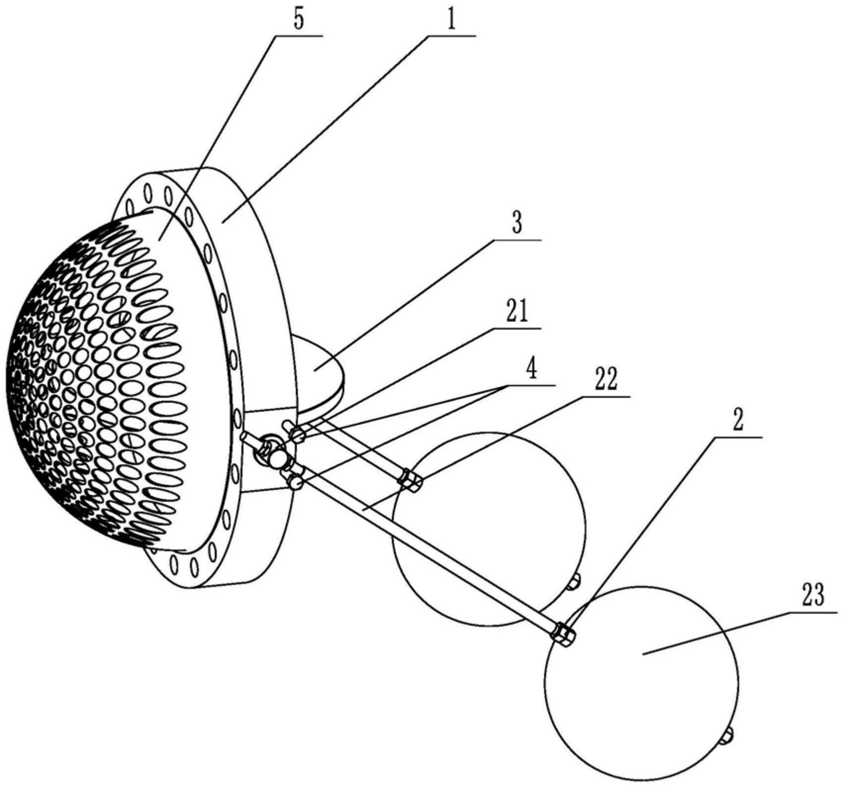
    1. A double-clip type float valve, comprising a valve body and a driving mechanism. The valve body is provided with a through medium channel in the axial direction. It is characterized in that the valve body is tubular and further comprises a butterfly plate that fits and seals with the inner wall of the medium channel. The driving mechanism comprises a valve shaft passing through the valve body and connected to the butterfly plate, a valve rod connected to the outer end of the valve shaft in the radial direction, and a float connected to the valve rod. The valve rod is provided with a limit bolt threadedly connected to the valve body in the swinging direction. The butterfly plate is rotatable relative to the valve body. The front end of the valve body located at the inlet of the medium channel is provided with a filter screen. The filter screen is hollow and hemispherical. The end surface of the valve body opposite the filter screen is provided with an annular groove. The open end of the filter screen is provided with a convex edge embedded in the annular groove.

    2. A wafer-type float valve according to claim 1, characterized in that the valve rod penetrates one end of the valve shaft located outside the valve body, and is threadedly engaged with the valve rod through a nut to clamp the valve shaft and achieve positioning of the valve rod.

    3. A wafer-type ball valve according to claim 2, characterized in that a step is provided at the position on the valve shaft connected to the valve body, a groove is provided at the position on the outer circumferential wall of the valve body corresponding to the step, and a gland is sleeved on the valve shaft, which is threadably connected to the groove and abuts against the step.

    4. A wafer-type ball valve according to claim 3, characterized in that a sealing groove is provided on the side of the groove facing the butterfly plate, and a sealing ring sleeved on the valve shaft is arranged in the sealing groove.

    5. A wafer-type ball valve according to claim 1, characterized in that an inner groove is provided on the side wall within the annular groove, and an elastic snap ring, which is used to press the convex edge and is compatible with the inner groove, is provided within the annular groove.

    6. A wafer-type ball valve according to claim 5, characterized in that the bottom of the convex edge is provided with a plurality of protrusions arranged around the center of the filter screen, and the annular groove is provided with a limiting groove adapted to the protrusions.

    7. A wafer-type float valve according to claim 6, characterized in that the protrusion is hemispherical. 8. A wafer-type float valve according to claim 7, characterized in that a clamping groove is provided at the junction of the protrusion and the protruding edge, and a clamping block adapted to the clamping groove is provided at the opening of the limiting groove.