Your location:

/ Valve products / ball valve / floating ball valve / Q41F Manual Ball Valve
全国销售热线:0577-67378222

Product classification of Kaiweixi

KAI WEI XI CHAN PIN FEN LEI
  • Q41F Manual Ball Valve

  • More floating ball valve>>

  • More ball valve>>

  • More valve>>

Contact Us
  • Phone:+86(577)6730 7899
  • Mobile:+86 189 6779 6135
  • Fax:+86(577)6738 7099
  • Email:Yannie@kaiweixi.com
  • Address:
  • Website:https://www.kaiweixi.com
Other valve products you may need
  • Q41F Flange Ball Valve
  • Q41Y 3PCS Forged Steel Ball Valve
  • Q41TC Ceramic Ball Valve
  • Q671F Pneumatic Wafer Ball Valve
  • Q941F Electric Floating Ball Valve
Q41F Manual Ball Valve

Q41F Manual Ball Valve

  • Model:Q41F-16P/Q41F-16R/Q41F-25P/Q41F-40P/Q41F-64P/Q41F-25R/Q41F-40R/Q41F-64R
  • Specification:DN15-DN250
  • Temperature:≤350℃
  • Medium:Water, Gas, Oil
  • Pressure:PN16-64
  • Connection method:flange
  • Driving method:manual
  • Material:stainless steel、cast steel, Bronze
x

Add QR code to serve you!

x

Add QR code to serve you!

x

Add QR code to serve you!

x
Q41F Manual Ball ValveOverview

Q41F Manual Ball Valve Overview

The Q41F Manual Ball Valve is a versatile industrial ball valve with flange connections, designed for manual operation to open or close the flow. The valve body is typically made of cast steel, stainless steel, or cast iron. A 90-degree rotation of the handle drives the stem to actuate the ball, enabling rapid shut-off or flow restoration. The seat utilizes soft sealing materials such as PTFE to ensure reliable sealing. With a simple structure and intuitive operation, this valve is suitable for media including water, steam, oil, and non-corrosive fluids, with a typical working pressure range of PN16 to PN40. It is widely used in petroleum and chemical industries, power generation, water supply and drainage systems, and general industrial pipelines.

Q41F Manual Ball Valve Product Image


Q41F Manual Ball ValveCharacteristic

Q41F Manual Ball Valve Features

1. Simple and Reliable Manual Operation:  

  Operated by rotating the handle 90 degrees directly to open or close the valve. The intuitive and straightforward design requires no external power source, making it suitable for applications without automation requirements.

2. Stable Installation with Flange Connection:  

  Equipped with standard flange connections for easy installation and excellent sealing performance, ensuring compatibility with various industrial pipeline systems.

3. Excellent Soft Sealing Performance:  

  The PTFE seat forms a soft seal with the ball, providing reliable sealing with low leakage rates and a long service life.

4. Compact Structure and Easy Maintenance:  

  The simple valve structure with fewer components results in low failure rates and minimal daily maintenance. Sealing components can be replaced conveniently when needed.

5. Cost-Effective and Wide Applicability:  

  Low manufacturing costs and suitability for a variety of non-corrosive media make it a highly cost-effective basic shut-off device in industrial pipeline systems.

Q41F Manual Ball Valvestructure principle

Q41F Manual Ball Valve Structure Diagram

Parts Name Material List

NO.NameMaterial
1bodystainless steel、cast steel
2ballstainless steel、cast steel
3seal gasketPTFE、Poly
4packingPTFE、Flexible Graphite
5stemstainless steel、cast steel


Q41F Manual Ball Valvetechnology parameter
Performance Specification
Nominal Pressure1.6-6.4Mpa
Shell Test2.4-9.6
Seal Test1.8-7.04
Suitable Temp.350


Q41F Manual Ball Valvestandard size

Dimensions Standard Requirements

1. The structural length of the valve shall conform to the standard GB/T12221.

2. The connecting flange shall conform to the standard GB9113.

Q41F Manual Ball Valve View Drawing

Q41F Manual Ball Valve Dimensions Table

DNDD:D2D31bn-dLHW
15134565952144-1413075130
201955751052144-1414084170
252565851152144-1415090170
3232781001352164-18165107200
4038851101453164-18180127250
50511001251603164-18200140250
65641201451803184-18220164350
80761351601953208-18250177350
1001021551802153208-18280206420
1251271852102453228-18320292700
1501522102402803248-233603201000
20020326529533532612-234003651300
25025432035540533012-254504201800


Articles related to technology research and development
  • Wafer-type ball valve patented

       The utility model provides a wafer-type float valve, which includes a valve body and a driving mechanism. The valve body is provided with a through medium channel in the axial direction, and is tubular in shape. It also includes a butterfly plate that fits and seals with the inner wall of the medium channel. The driving mechanism comprises a valve shaft that passes through the valve body and is connected to the butterfly plate, a valve rod connected to the outer end of the valve shaft in the radial direction, and a float ball connected to the valve rod. The valve rod is provided with a limit bolt that is threadedly connected to the valve body in the swinging direction. The butterfly plate can rotate relative to the valve body. The front end of the valve body at the inlet of the medium channel is provided with a filter screen, which is hollow and hemispherical in shape. The end face of the valve body opposite the filter screen is provided with an annular groove, and the open end of the filter screen is provided with a raised edge that is embedded in the annular groove. The utility model can filter the medium, is simple to install, time-saving, labor-saving, small in size, widely applicable, and can reduce the impact force of the medium on the butterfly plate.
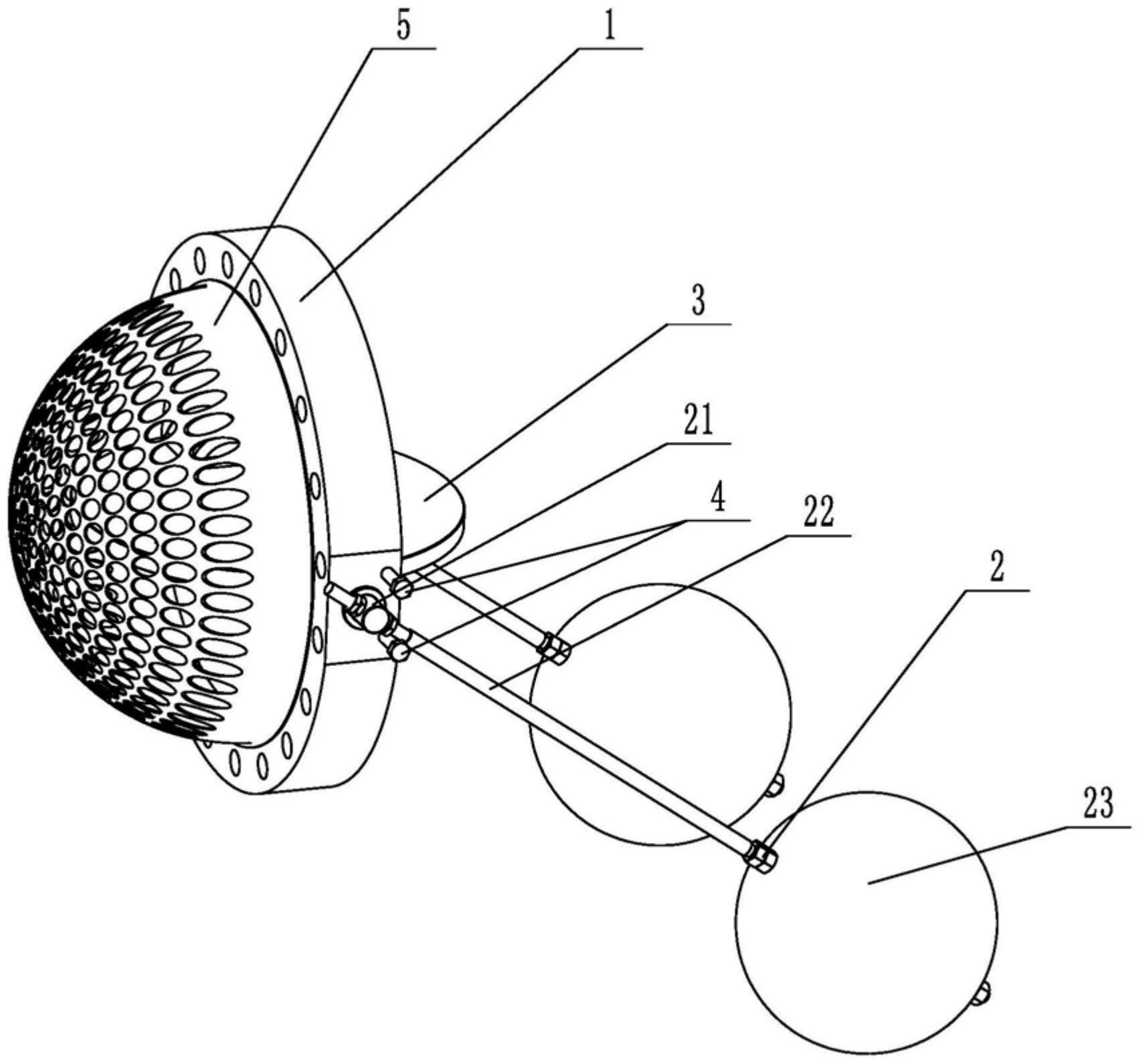
    1. A double-clip type float valve, comprising a valve body and a driving mechanism. The valve body is provided with a through medium channel in the axial direction. It is characterized in that the valve body is tubular and further comprises a butterfly plate that fits and seals with the inner wall of the medium channel. The driving mechanism comprises a valve shaft passing through the valve body and connected to the butterfly plate, a valve rod connected to the outer end of the valve shaft in the radial direction, and a float connected to the valve rod. The valve rod is provided with a limit bolt threadedly connected to the valve body in the swinging direction. The butterfly plate is rotatable relative to the valve body. The front end of the valve body located at the inlet of the medium channel is provided with a filter screen. The filter screen is hollow and hemispherical. The end surface of the valve body opposite the filter screen is provided with an annular groove. The open end of the filter screen is provided with a convex edge embedded in the annular groove.

    2. A wafer-type float valve according to claim 1, characterized in that the valve rod penetrates one end of the valve shaft located outside the valve body, and is threadedly engaged with the valve rod through a nut to clamp the valve shaft and achieve positioning of the valve rod.

    3. A wafer-type ball valve according to claim 2, characterized in that a step is provided at the position on the valve shaft connected to the valve body, a groove is provided at the position on the outer circumferential wall of the valve body corresponding to the step, and a gland is sleeved on the valve shaft, which is threadably connected to the groove and abuts against the step.

    4. A wafer-type ball valve according to claim 3, characterized in that a sealing groove is provided on the side of the groove facing the butterfly plate, and a sealing ring sleeved on the valve shaft is arranged in the sealing groove.

    5. A wafer-type ball valve according to claim 1, characterized in that an inner groove is provided on the side wall within the annular groove, and an elastic snap ring, which is used to press the convex edge and is compatible with the inner groove, is provided within the annular groove.

    6. A wafer-type ball valve according to claim 5, characterized in that the bottom of the convex edge is provided with a plurality of protrusions arranged around the center of the filter screen, and the annular groove is provided with a limiting groove adapted to the protrusions.

    7. A wafer-type float valve according to claim 6, characterized in that the protrusion is hemispherical. 8. A wafer-type float valve according to claim 7, characterized in that a clamping groove is provided at the junction of the protrusion and the protruding edge, and a clamping block adapted to the clamping groove is provided at the opening of the limiting groove.