Your location:

/ Valve products / ball valve / floating ball valve / Q21Y Pneumatic High-Pressure Ball Valve
全国销售热线:0577-67378222

Product classification of Kaiweixi

KAI WEI XI CHAN PIN FEN LEI
  • Q21Y Pneumatic High-Pressure Ball Valve

  • More floating ball valve>>

  • More ball valve>>

  • More valve>>

Contact Us
  • Phone:+86(577)6730 7899
  • Mobile:+86 189 6779 6135
  • Fax:+86(577)6738 7099
  • Email:Yannie@kaiweixi.com
  • Address:
  • Website:https://www.kaiweixi.com
Other valve products you may need
  • Q41F Flange Ball Valve
  • Q41Y 3PCS Forged Steel Ball Valve
  • Q41TC Ceramic Ball Valve
  • Q671F Pneumatic Wafer Ball Valve
  • Q941F Electric Floating Ball Valve
Q21Y Pneumatic High-Pressure Ball Valve

Q21Y Pneumatic High-Pressure Ball Valve

  • Model:Q21Y-16P/Q21Y-25P/Q21Y-40P/Q21Y-64P
  • Specification:DN10-DN25
  • Temperature:≤425℃
  • Medium:Water、gas、oil
  • Pressure:PN16,PN25,PN40,PN64
  • Connection method:welded
  • Driving method:pneumatic
  • Material:stainless steel,carbon steel,forged stainless steel
x

Add QR code to serve you!

x

Add QR code to serve you!

x

Add QR code to serve you!

x
Q21Y Pneumatic High-Pressure Ball ValveOverview

Q21Y Pneumatic High-Pressure Ball Valve Overview

The Q21Y Pneumatic High-Pressure Ball Valve is a high-pressure specialized ball valve driven by a pneumatic actuator, designed to meet the requirements of high-pressure working conditions. The valve body is made of forged steel or stainless steel, and features a metal hard-seal or reinforced sealing structure internally. The pneumatic actuator drives the stem to rotate the ball 90 degrees for rapid opening and closing. This valve is specifically designed for high-pressure gases, liquids, and corrosive media, with a working pressure of up to PN160 or higher. It is suitable for applications in petrochemicals, natural gas, high-pressure filling systems, and industrial automation, serving as key equipment for achieving rapid, reliable shut-off and automated control in high-pressure pipelines.

Q21Y Pneumatic High-Pressure Ball Valve Product Image

Q21Y Pneumatic High-Pressure Ball ValveCharacteristic

Q21Y Pneumatic High-Pressure Ball Valve Features

1. Reliable High-Pressure Sealing: Utilizes metal hard-seal or reinforced composite sealing structures, offering high-pressure resistance and wear resistance, ensuring reliable sealing and long service life under high-pressure differential conditions.

2. Rapid Response of Pneumatic Actuation: Equipped with single-acting or double-acting pneumatic actuators, enabling fast opening and closing (typically within seconds) with sensitive response, suitable for automated control and emergency shut-off.

3. Compact Structure and High Pressure Resistance: The valve body is made of forged steel or high-strength stainless steel, featuring a compact design and high-pressure-bearing capacity, ideal for high-pressure and high-frequency operation conditions.

4. Comprehensive Safety Protection Design: Typically includes fireproof and anti-static structures, with a stem anti-blowout design. Some models support automatic reset in case of air source failure (single-acting spring return).

5. Intelligent Control and Easy Maintenance: Can be configured with accessories such as solenoid valves and limit switches to achieve remote control and status feedback. The modular design facilitates maintenance and seal replacement.

Q21Y Pneumatic High-Pressure Ball Valvestructure principle

Q21Y Pneumatic High-Pressure Ball Valve Structure Diagram

Parts Name Material List

NO.NameMaterial
1bodystainless steel
2ballstainless steel
3seal gasketPTFE
4packingPTFE
5Stemstainless steel


Q21Y Pneumatic High-Pressure Ball Valvetechnology parameter
Performance Specification
Nominal Pressure1.6-6.4Mpa
Shell Test2.4-9.6
Seal Test1.8-7.04
Suitable Temp.425


Q21Y Pneumatic High-Pressure Ball Valvestandard size

Dimensions Standard Requirements

1. The structural length of the valve shall conform to the standard GB/T12221.

2. The connecting flange shall conform to the standard GB9113.

Q21Y Pneumatic High-Pressure Ball Valve View Drawing

Q21Y Pneumatic High-Pressure Ball Valve Dimensions Table

型号 ModelDNPN (bar)L1L2Bb1h1h2h4h5h6SW1
Q21Y0450040174266013.533408016309
Q21Y0660040174266013.533406016309
Q21Y085004219932701638607018609
Q21Y105004219832701636607018609
Q21Y135004719835701838607018809
Q21Y164004823738841945602020909
Q21Y203156023748842555602021912
Q21Y2531565237678428.564602022812
Q21Y32316842907510837.5846010828214
Q21Y40315912908510842.5956010829314
Q21Y5031510029010410852112.560108310.514


Articles related to technology research and development
  • Wafer-type ball valve patented

       The utility model provides a wafer-type float valve, which includes a valve body and a driving mechanism. The valve body is provided with a through medium channel in the axial direction, and is tubular in shape. It also includes a butterfly plate that fits and seals with the inner wall of the medium channel. The driving mechanism comprises a valve shaft that passes through the valve body and is connected to the butterfly plate, a valve rod connected to the outer end of the valve shaft in the radial direction, and a float ball connected to the valve rod. The valve rod is provided with a limit bolt that is threadedly connected to the valve body in the swinging direction. The butterfly plate can rotate relative to the valve body. The front end of the valve body at the inlet of the medium channel is provided with a filter screen, which is hollow and hemispherical in shape. The end face of the valve body opposite the filter screen is provided with an annular groove, and the open end of the filter screen is provided with a raised edge that is embedded in the annular groove. The utility model can filter the medium, is simple to install, time-saving, labor-saving, small in size, widely applicable, and can reduce the impact force of the medium on the butterfly plate.
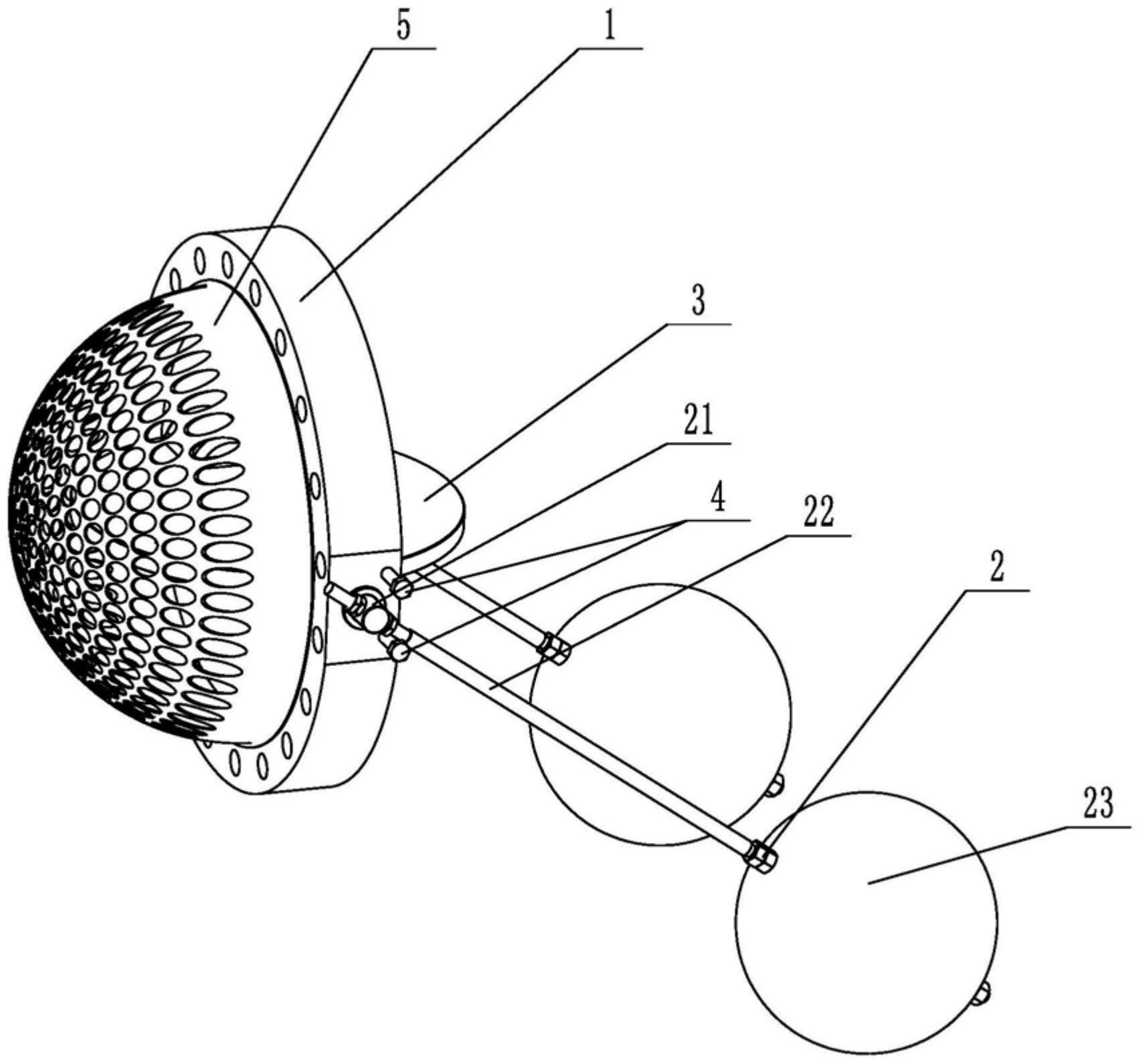
    1. A double-clip type float valve, comprising a valve body and a driving mechanism. The valve body is provided with a through medium channel in the axial direction. It is characterized in that the valve body is tubular and further comprises a butterfly plate that fits and seals with the inner wall of the medium channel. The driving mechanism comprises a valve shaft passing through the valve body and connected to the butterfly plate, a valve rod connected to the outer end of the valve shaft in the radial direction, and a float connected to the valve rod. The valve rod is provided with a limit bolt threadedly connected to the valve body in the swinging direction. The butterfly plate is rotatable relative to the valve body. The front end of the valve body located at the inlet of the medium channel is provided with a filter screen. The filter screen is hollow and hemispherical. The end surface of the valve body opposite the filter screen is provided with an annular groove. The open end of the filter screen is provided with a convex edge embedded in the annular groove.

    2. A wafer-type float valve according to claim 1, characterized in that the valve rod penetrates one end of the valve shaft located outside the valve body, and is threadedly engaged with the valve rod through a nut to clamp the valve shaft and achieve positioning of the valve rod.

    3. A wafer-type ball valve according to claim 2, characterized in that a step is provided at the position on the valve shaft connected to the valve body, a groove is provided at the position on the outer circumferential wall of the valve body corresponding to the step, and a gland is sleeved on the valve shaft, which is threadably connected to the groove and abuts against the step.

    4. A wafer-type ball valve according to claim 3, characterized in that a sealing groove is provided on the side of the groove facing the butterfly plate, and a sealing ring sleeved on the valve shaft is arranged in the sealing groove.

    5. A wafer-type ball valve according to claim 1, characterized in that an inner groove is provided on the side wall within the annular groove, and an elastic snap ring, which is used to press the convex edge and is compatible with the inner groove, is provided within the annular groove.

    6. A wafer-type ball valve according to claim 5, characterized in that the bottom of the convex edge is provided with a plurality of protrusions arranged around the center of the filter screen, and the annular groove is provided with a limiting groove adapted to the protrusions.

    7. A wafer-type float valve according to claim 6, characterized in that the protrusion is hemispherical. 8. A wafer-type float valve according to claim 7, characterized in that a clamping groove is provided at the junction of the protrusion and the protruding edge, and a clamping block adapted to the clamping groove is provided at the opening of the limiting groove.